Switch mechanism

A technology of switch mechanism and electric switch, which is applied in the direction of electric switch, harvester, portable motorized device, etc., to achieve the effect of easy operation

Inactive Publication Date: 2005-11-02
GMCA PTY LIMITED
View PDF2 Cites 5 Cited by
  • Summary
  • Abstract
  • Description
  • Claims
  • Application Information

AI Technical Summary

Problems solved by technology

This action alone cannot operate the electric switch, because the slide bar is still locked on the button and cannot be moved

Method used


Image

  • Switch mechanism
  • Switch mechanism
  • Switch mechanism

Examples


Embodiment Construction

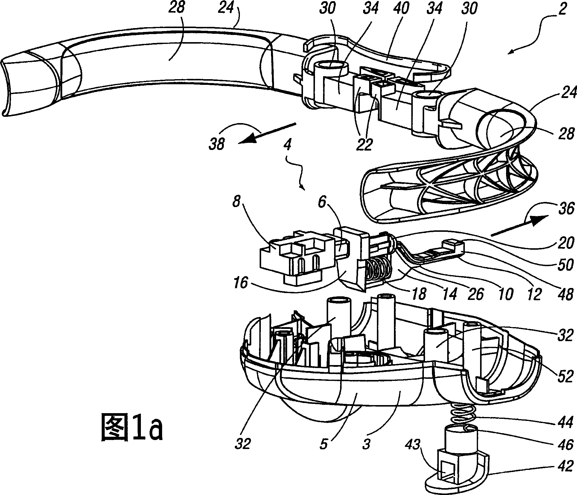
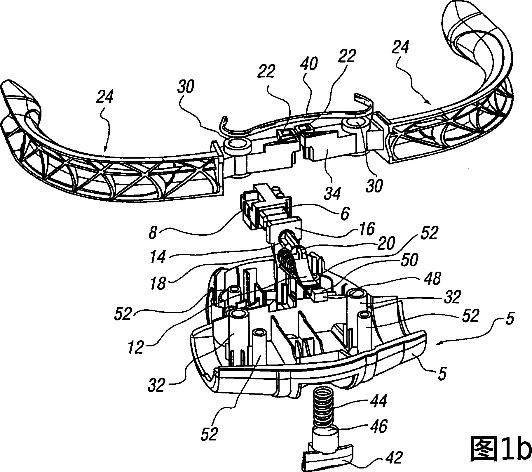
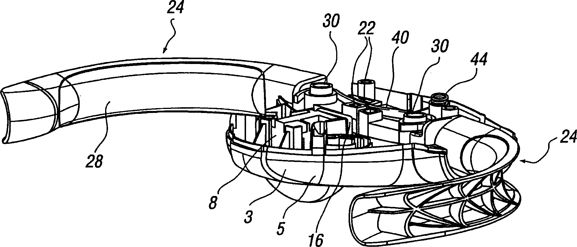
[0039] Referring firstly to Figures 1a-2b, a switch mechanism 2 for operating an electrical switch 4 is shown. The switching mechanism is located in the housing 3 and generally comprises two interengageable parts, namely a first part 5 and a second part (not shown for clarity).

[0040] The electric switch 4 comprises a switch part 6, which is partly located in the housing 8, and is slidable relative to the housing between a retracted "on position" and an extended "off position", wherein, in Electrical contact can be made in the "on position" and no electrical contact can be made in the "off position". When the electrical contact is formed, the electrical products connected or communicated with the electrical switch 4 can be powered.

[0041] The switch operating device 10 is provided for operating the electric switch 4 in order to move it between said on and off positions. The switch operator 10 is in the form of a slide bar and includes a latch portion 12 , a slide bar bod...


PUM


Abstract

A switch mechanism is provided for the actuation of an electrical switch, the electrical switch being movable between an on position, wherein electrical contact is made, and an off position, wherein no electrical contact is made. The switch mechanism includes a plunger which is movable between first and second positions to move said switch between said on and off positions respectively upon actuation thereof, and resilient biasing means for biasing the plunger for movement from said second position to said first position. The resilient biasing means are provided in a substantially compressed or biased form when plunger is in the second off position.

Description

technical field [0001] The invention relates to a switch mechanism. Background technique [0002] It is often the case that due to the safety requirements associated with the use of certain electrical products such as power tools, lawnmowers and / or similar devices, there is provided a switching mechanism on said electrical appliances which can be used to control their operation, the switching mechanism The "on" state can be moved from the "on" state to the "off" state when the user releases his hand from the appliance. The purpose of the above requirements is to prevent damage to the electrical appliance if the user accidentally loses control of the appliance, for example if the user accidentally drops a power tool and The damage caused by the continued action to the user is prevented or minimized. [0003] Another safety requirement of some electrical products is the provision of means to minimize the possibility of the electrical appliance being accidentally switched on,...

Claims


Application Information

Patent Timeline
Patent Type & Authority Applications(China)
IPC IPC(8): H01H3/02H01H3/20H01H9/06H01H9/20H01H21/24
CPCH01H2009/068A01D34/828H01H3/20A01D34/6818H01H9/06
Inventor 基思·帕克
Owner GMCA PTY LIMITED
Why Eureka
Try Eureka