Triphibian flying car based on lifting tech. of wing

A flying car and wing technology, applied in the field of amphibious flying cars, can solve the problems of limited results and high costs

Inactive Publication Date: 2005-11-09
朱上翔
View PDF0 Cites 5 Cited by
  • Summary
  • Abstract
  • Description
  • Claims
  • Application Information

AI Technical Summary

Problems solved by technology

For decades, although many individuals, institutions or companies have spent a lot of manpower and material resources in an attempt to overcome this seemingly uncomplicated dual-purpose vehicle, the results have been limited so far.
In September 2004, NASA and Boeing announced that they had mastered the principle of flying cars, but it will not be possible to put them into practical use until at least 25 years later.
The result is that there are many problems and the cost is too high

Method used


Image

  • Triphibian flying car based on lifting tech. of wing
  • Triphibian flying car based on lifting tech. of wing
  • Triphibian flying car based on lifting tech. of wing

Examples


Embodiment Construction

[0018] combine Figure 1 to Figure 10 , two embodiments of the present invention are described in detail.

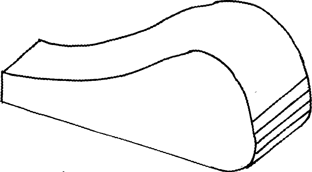
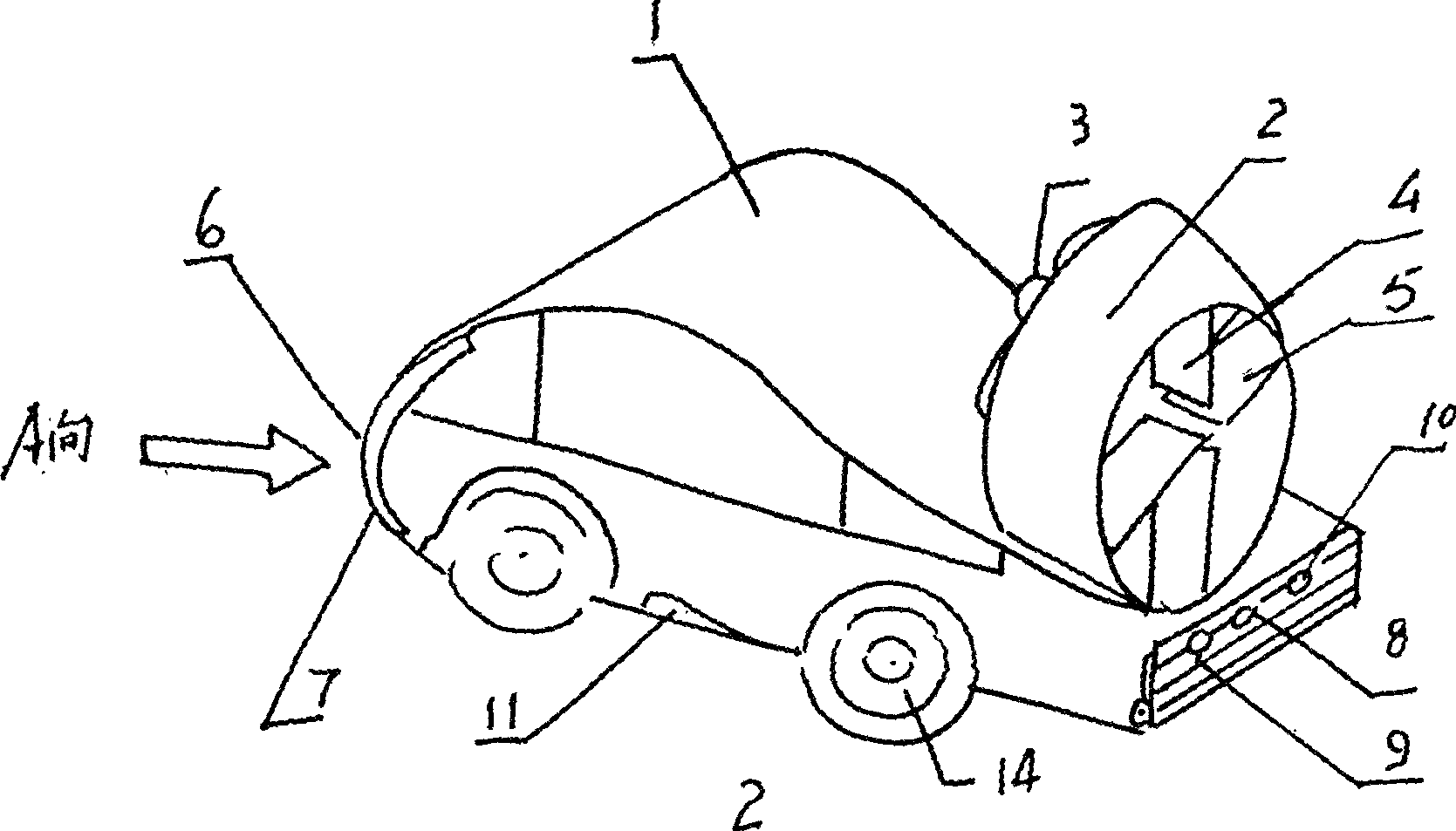
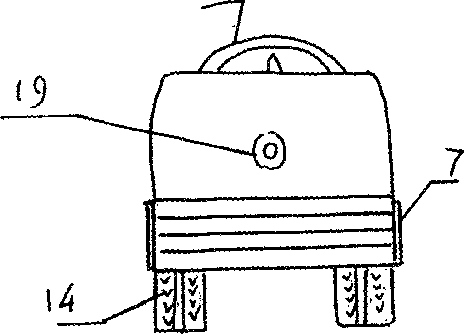
[0019] figure 1 It is the flying car body of the present invention, and the longitudinal section 1 is a wing section shape with relative thickness and large lift-to-drag ratio. 3 awning wings 2, 3 and 4 for increasing the lift are installed above the vehicle body. The canopy fins are parallel to the upper airfoil of the reference airfoil, and are structurally connected mechanically with the body of the basic airfoil (ie, the vehicle body). Three canopy wings form three left and right sealed ducts. Due to the two-dimensional effect and the effect of the canopy, this body has a high lift coefficient and a large lift-to-drag ratio. figure 2 It is the schematic diagram of the principle of the first embodiment of the present invention-type 1 flying car. It is characterized in that a lifting body 1 adds a tail ring wing 2 as a longitudinal and lateral stabilizing device,...


PUM


Abstract

A triphibian flying car based on the lift performance of wing is composed of a main body whose longitudinal cross-section is similar to that of wing for generating great lift force, a culvert-type propeller, a slipe-flow helm and surficial adsorptive layer for decreasing resistance. Its two models are disclosed.

Description

technical field [0001] The invention relates to an amphibious flying car capable of running on land, flying in the air and cruising in water, which belongs to the multifunctional transporter in the fields of aviation and automobiles. Background technique: [0002] Since the invention of powered aircraft by human beings 100 years ago, scientific and technological workers have been devoting themselves to developing a multi-functional means of transport that has both the functions of an aircraft and an automobile. There have been a large number of invention patents or utility model patents related to flying automobiles at home and abroad. . So far, many countries have successively developed many flying car prototypes. For example, the M400 flying car developed by the Moller Company of the United States, the Gridlock Commuter, the concept car of NASA (the personal transportation tool for commuters), the flying car with rotors of the Boeing Aircraft Company, the City Eagle of Is...

Claims


Application Information

Patent Timeline
IPC IPC(8): B60F5/00
Inventor 朱上翔
Owner 朱上翔
Why Eureka
Try Eureka