
An airfoil for a wind rotor blade layer of a wind power generating set

A technology for wind turbines and wind rotor blades, which is applied in the field of wind rotor blade layers, and can solve problems such as large airfoil resistance, air separation, and reduced economic benefits of wind turbine rotors

Active Publication Date: 2021-12-14
LANZHOU UNIVERSITY OF TECHNOLOGY
View PDF7 Cites 0 Cited by
  • Summary
  • Abstract
  • Description
  • Claims
  • Application Information

AI Technical Summary

Problems solved by technology

However, the current special airfoils for wind turbines also have the problem of air separation at high angles of attack, so the resistance of the airfoils is relatively large, which reduces the economic benefits of wind turbine rotors

Method used


Image

  • An airfoil for a wind rotor blade layer of a wind power generating set
  • An airfoil for a wind rotor blade layer of a wind power generating set
  • An airfoil for a wind rotor blade layer of a wind power generating set

Examples


Embodiment Construction

[0016] In order to enable those skilled in the art to better understand the technical solutions of the present invention, the present invention will be further described in detail below in conjunction with the accompanying drawings and specific embodiments. Hereinafter, embodiments of the present invention will be described in detail, examples of which are shown in the accompanying drawings, wherein the same or similar reference numerals denote the same or similar elements or elements having the same or similar functions throughout. The embodiments described below by referring to the figures are exemplary only for explaining the present invention and should not be construed as limiting the present invention. Those skilled in the art will understand that unless otherwise stated, the singular forms "a", "an", "said" and "the" used herein may also include plural forms. It should be further understood that the word "comprising" used in the description of the present invention refe...


PUM


Abstract

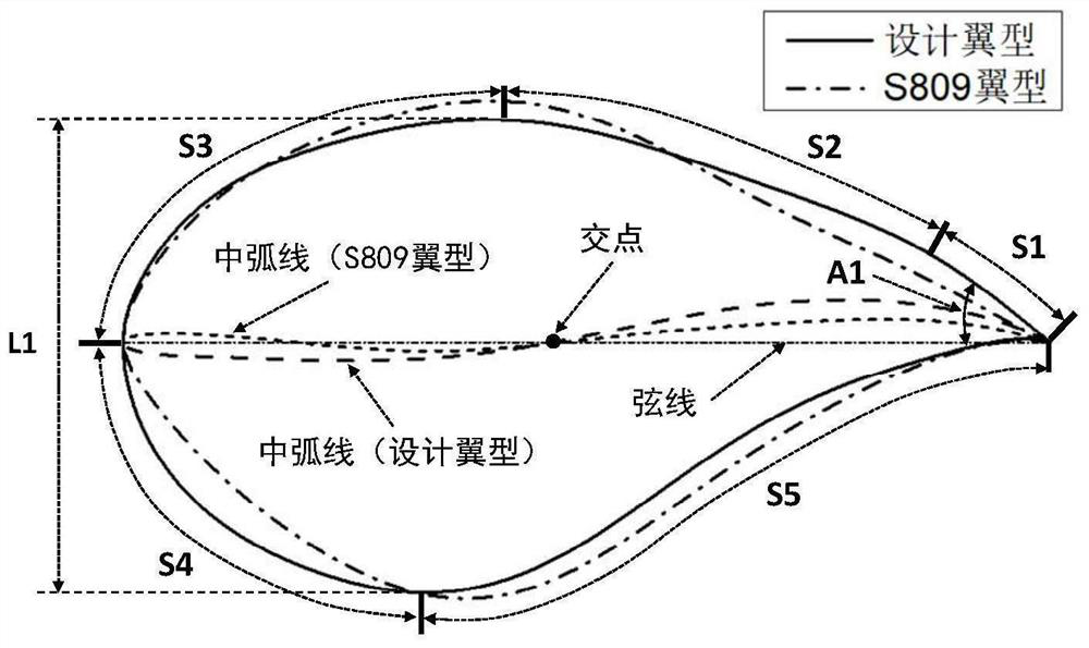
The embodiment of the invention discloses an airfoil for a wind rotor blade layer of a wind power generating set, which relates to the technical field of aerodynamics, can improve the lift coefficient, realize a larger stall angle of attack and smaller resistance, thereby improving wind power The wind energy absorption efficiency of the wind turbine of the generator set. The invention comprises: S1 section and S5 section are the trailing edge contraction sections of the airfoil, S1 section and S5 section are closed and connected at the trailing edge position of the airfoil; S2 section is the smooth transition section of the upper surface of the airfoil, respectively Closed connection with section S3, with section S5 on the lower surface, the mid-arc curvature of the airfoil is designed to be larger; section S3 is the leading edge section on the upper surface of the airfoil, connected to section S2 and section S4; section S4 is connected to the lower surface of the airfoil The leading edge section of the surface, connected with the S3 section and the S5 section, has a larger curvature compared with the S809 airfoil. The invention is suitable for the airfoil with high lift-to-drag ratio in the design of the wind turbine blade of the wind power generating set.

Description

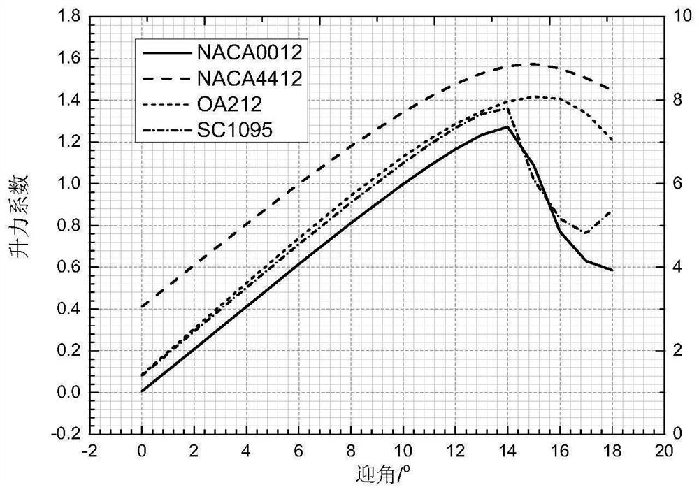
technical field [0001] The invention relates to the technical field of aerodynamics, in particular to an airfoil which is mainly applied in the field of wind power generation and can improve the blade layer of a wind rotor of a wind power generating set. Background technique [0002] For the geometric shape of a wind blade, the airfoil is the "gene" of the blade, and its aerodynamic performance directly affects the aerodynamic performance of the wind turbine blade. Therefore, the design of the aerodynamic shape of the wind turbine rotor blade is inseparable from the airfoil design. Before the 1980s, the airfoils of wind turbines often used aviation airfoils. However, if figure 1 As shown, the aeronautical airfoil is usually designed under pressure-sonic conditions, and the aerodynamic performance cannot be effectively guaranteed under low-speed conditions. In addition, there are disadvantages that the thickness is small and cannot meet the structural requirements. The stal...

Claims


Application Information

Patent Timeline
Patent Type & Authority Patents(China)
IPC IPC(8): F03D1/06
CPCF03D1/0675Y02E10/72
Inventor 王清李德顺
Owner LANZHOU UNIVERSITY OF TECHNOLOGY
Learn More