

Large-sized air-cooled fan blade wity synergistic antivibration action
A cooling fan and blade technology, which is applied to the components of the pumping device for elastic fluid, mechanical equipment, machine/engine, etc., can solve the fatigue damage, the disadvantage of large-scale air cooling fan efficiency and operation reliability, and the reduction of fan operation efficiency. and other problems to achieve the effect of reducing vibration, reducing efficiency loss and improving operating efficiency
Inactive Publication Date: 2005-10-05
JIANGSU SHENHAI GRP CO LTD
View PDF0 Cites 0 Cited by
- Summary
- Abstract
- Description
- Claims
- Application Information
AI Technical Summary
Problems solved by technology
The violent flow of this airflow from the high pressure area around the tip of the blade to the negative pressure area is extremely detrimental to the efficiency and operational reliability of large air-cooled fans. Due to this flow, the pressure difference between the upper and lower sides of the blade tip is reduced, that is, the The lift force L makes the operation efficiency of the fan drop greatly; during the flow process, the airflow in the high-pressure area flows to the low-pressure area (negative pressure area) at a high speed, which forms a large pulse impact force on the air cylinder, making the large-scale wind The barrel produces large vibration, which is easy to be damaged by fatigue
Method used
View moreImage
Smart ImageViewing Examples

Examples
Embodiment
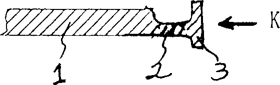
[0012] A large-scale air-cooled fan blade with synergistic and anti-vibration effects, including a blade 1, an airfoil section 2 with a relatively tapered thickness is arranged at the tip of the blade 1, and the outer side of the airfoil section 2 with a tapered thickness is connected with a vertically arranged choke plate 3. The spoiler 3 is integrated with the airfoil section 2 with tapered tip thickness, and the upper and lower ends of the spoiler 3 are respectively located above and below the airfoil section 2 with tapered tip thickness, that is, the spoiler 3 The airfoil section 2 with tapered thickness of the blade tip is connected in a " " shape.
Login to View More PUM
 Abstract
The invention discloses a fin of large air cooling fan with enhanced shock proof function, which includes fin with a wing section set at the end of the fin with its relative thickness gradually decreases, flow shielding plate linked at the out side of the wing section. The invention effectively enhances the service efficiency of the fan and reduces the shock on fan and ram.
Description
Technical field: [0001] The invention relates to a blade of an air cooling fan. Background technique: [0002] The working principle of the fan blade is based on the air forming a pressure difference between the upper and lower surfaces of the blade to generate lift. The formula for calculating the lift force L per unit length of the tip of the blade: L=1 / 2ρC L u 2 b, L is lift (N), ρ is density (kg / m 3 ), b is the chord width (m), u t is the blade tip rotation speed (m / s), u is the blade tip airflow combined velocity (m / s), v is the airflow axial velocity (m / s), u=v 2 + u t 2 ; Since the blade is in the tip region, the tip velocity u t reaches the maximum value, so the resultant speed u also reaches the maximum value; in the design of the fan blade, the C of the blade tip area L Generally, a higher value is also taken, so the lift force L generally takes a higher value at the tip of the blade. That is, a huge pressure difference is formed on and below the blade tip...
Claims
Login to View More Application Information
Patent Timeline
 Patent Type & AuthorityApplications(China)
IPC IPC(8): F04D29/30
Inventor周忠张国荣李士成
OwnerJIANGSU SHENHAI GRP CO LTD