Photovoltaic cell cutting method and cell manufactured by method

A technology of photovoltaic cells and cutting methods, applied in manufacturing tools, semiconductor/solid-state device manufacturing, circuits, etc., can solve problems such as adverse effects of equipment working environment, reduced efficiency of hit cells, and reduced package power of components, so as to increase power and reduce Effects of destroying and improving mechanical strength

Inactive Publication Date: 2020-08-28
RISEN ENERGY
View PDF9 Cites 10 Cited by
  • Summary
  • Abstract
  • Description
  • Claims
  • Application Information

AI Technical Summary

Problems solved by technology

According to the existing technology, because the cutting temperature is too high, it will often affect the efficiency of the surrounding cells, thereby reducing the packaging power of the components; especially for Hit cells, because the temperature above 220°C will basically destroy its amorphous silicon film layer, Using the current laser cutting method will reduce the efficiency of the hit cell more
Moreover, the current cutting method will cause the silicon material to form a large amount of dust during the cutting process, which will adversely affect the working environment around the equipment.

Method used


Image

  • Photovoltaic cell cutting method and cell manufactured by method
  • Photovoltaic cell cutting method and cell manufactured by method
  • Photovoltaic cell cutting method and cell manufactured by method

Examples


Embodiment 1

[0032] A method for cutting photovoltaic cells, comprising the steps of:

[0033] 1. Place the cell to be cut in the laser scribing area;

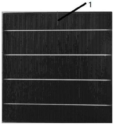
[0034] 2. Use the first laser to form the first cutting line 1 on the edge of the cell at the cell cutting position. The length of the crack in the first cutting line 1 is 0.3 cm, and the cutting depth is 70% of the thickness of the cell;

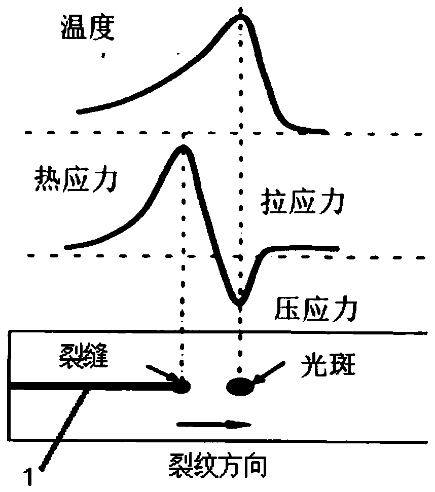
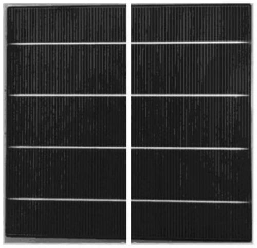
[0035] 3. Using the second laser, the spot is heated along the first cutting line 1 in front of the crack. The principle can be referred to figure 1 , an uneven temperature field and temperature gradient are formed at the spot position, and the temperature gradient induces the generation of thermal stress, so that the crack cracks the battery sheet along the moving direction of the spot;

[0036] When the light spot acts on the silicon wafer, the cutting position is cooled by air cooling at the same time to reduce the temperature at which the laser reaches the surface of the battery. In this example, t...

Embodiment 2

[0040] A method for cutting photovoltaic cells, comprising the steps of:

[0041] 1. Place the cell to be cut in the laser scribing area;

[0042] 2. Use the first laser to form the first cutting line 1 on the edge of the cell at the cell cutting position. The length of the crack in the first cutting line 1 is 2.5 cm, and the cutting depth is 50% of the thickness of the cell;

[0043] 3. Using the second laser, the spot is heated along the first cutting line 1 in front of the crack. The principle can be referred to figure 1 , an uneven temperature field and temperature gradient are formed at the spot position, and the temperature gradient induces the generation of thermal stress, so that the crack cracks the battery sheet along the moving direction of the spot;

[0044] When the light spot acts on the silicon wafer, liquid cooling is used to cool the cutting position at the same time, so as to reduce the temperature at which the laser reaches the surface of the battery. In th...

Embodiment 3

[0048] A method for cutting photovoltaic cells, comprising the steps of:

[0049]1. Place the cell to be cut in the laser scribing area;

[0050] 2. Use the first laser to form the first cutting line 1 on the edge of the cell at the cutting position of the cell. The length of the crack in the first cutting line 1 is 3 cm, and the cutting depth is 60% of the thickness of the cell;

[0051] 3. Using the second laser, the spot is heated locally in front of the crack along the first cutting line 1, forming an uneven temperature field and temperature gradient at the spot position, and the temperature gradient induces thermal stress, so that the crack along the The direction in which the light spot moves splits the cell;

[0052] When the light spot acts on the silicon wafer, the cutting position is cooled by air cooling at the same time to reduce the temperature at which the laser reaches the surface of the battery. The second laser cutting temperature is lower than 200°C, and the...


PUM

PropertyMeasurementUnit
lengthaaaaaaaaaa
lengthaaaaaaaaaa
lengthaaaaaaaaaa

Abstract

The invention discloses a photovoltaic cell cutting method, and further provides a battery piece which is obtained by cutting through the photovoltaic battery piece cutting method. The method comprises the steps of that 1, a cell to be cut is placed in a laser scribing area; 2, forming a first cutting line on the edge of the cutting position of the battery piece by using a first laser; and 3, a second laser is used, the light spot of the second laser is locally heated along the position in front of the crack of the first cutting line and moves and extends in the direction where the first cutting line is located and in the direction away from the edge, and meanwhile the heated position is cooled. The method has the advantages that the laser cutting temperature can be obviously reduced, no gasification or fusion is generated in the cutting process, so that no dust is generated, no slag chip or micro crack is generated on the cutting fracture surface, so that the mechanical properties ofthe battery and the assembly are improved, namely the mechanical strength is improved, for condition of an amorphous silicon film layer, the amorphous silicon film layer is prevented from being damaged, and efficiency loss of the battery piece is reduced.

Description

technical field [0001] The invention relates to the technical field of battery sheet cutting, in particular to a photovoltaic battery sheet cutting method and battery sheets produced by the method. Background technique [0002] In the photovoltaic market, half-cell modules are welcomed by customers due to their small electrical loss, high module power and efficiency, and quickly occupy the market. Half-chip module packaging is to cut the whole battery into half pieces by laser. At present, most of the lasers used are n-second infrared, and the temperature is as high as 1000°C to directly vaporize or melt the silicon in contact, thereby forming a V-shaped groove on the surface of the silicon chip. slot, and then mechanically break the sheet to form a half-sheet battery. According to the existing technology, because the cutting temperature is too high, it will often affect the efficiency of the surrounding cells, thereby reducing the packaging power of the components; especia...

Claims


Application Information

Patent Timeline
Patent Type & Authority Applications(China)
IPC IPC(8): B23K26/38B23K26/70H01L21/78
CPCB23K26/38B23K26/703H01L21/78
Inventor 蔡后敏刘亚峰黄晓胡剑鸣
Owner RISEN ENERGY
Why Eureka
Try Eureka