Check patentability & draft patents in minutes with Patsnap Eureka AI!

Capped flat end windings in an electrical machine

A technology of end windings and field windings, which is applied in the direction of windings, electric components, manufacturing motor generators, etc., and can solve problems such as the obstruction of cooling medium path discharge

Inactive Publication Date: 2005-11-09
GENERAL ELECTRIC CO
View PDF0 Cites 2 Cited by
  • Summary
  • Abstract
  • Description
  • Claims
  • Application Information

AI Technical Summary

Problems solved by technology

The end retaining ring or closing ring thus becomes an obstacle to the discharge of the cooling medium path through the rotor end winding

Method used


Image

  • Capped flat end windings in an electrical machine
  • Capped flat end windings in an electrical machine
  • Capped flat end windings in an electrical machine

Examples


Embodiment Construction

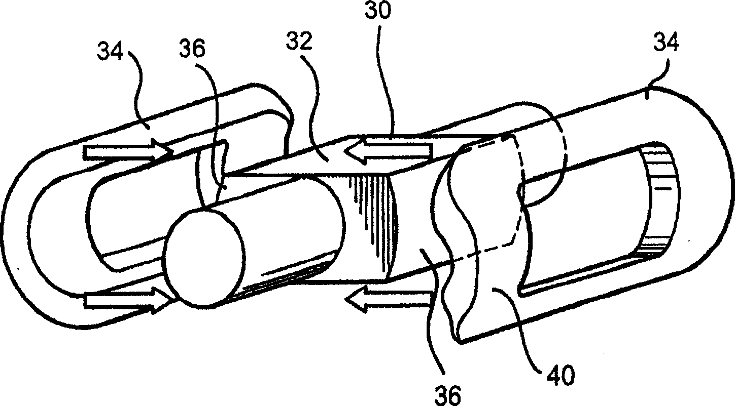
[0014] As depicted in FIG. 1 , generator 30 includes a multi-pole core 32 (a two-pole core is shown) and a plurality of winding assemblies 34 , one for each pole, and corresponding pole surfaces 36 . The construction and materials of the magnetic core 32 and winding assembly 34 are known. The prefabricated winding assembly 34 is disposed over the parallel side forgings forming the rotor body and is bent in an arc generally concentric with the rotor body. Although not shown, it will also be appreciated that the rotor is disposed within the stator, not shown, with an air gap between the inner surface of the stator and the outer surface of the rotor. The generator rotor shown in Figure 1 has end windings 40 extending arcuately over the mandrel at opposite ends of the rotor within the final assembly of the rotor body. The previously described rotor body is a carbon fiber rotor housing (CFRE), which offers several advantages over existing conventional generators which typically ha...


PUM


Abstract

End windings (40) of the field windings of a generator rotor body (47) are flattened. A cap (50) having a flat undersurface (52) overlies the flattened end windings and an enclosure ring (54) extends about the end windings and cap. Apertures (58) are formed through the cap in communication with gaps between the coils of the end windings and passageways (60) formed along the outer surface of the cap. The passageways and apertures form ventilation paths for a cooling medium flowing through the end windings outwardly into the air gap between the rotor body and stator.

Description

technical field [0001] The invention relates primarily to electric machines of the type having a rotor and field windings including end windings surrounding the rotor body, and in particular to end windings flattened across the pole width, together with a cooling medium diameter for the end windings Cover for outward flow ventilation. Background technique [0002] In an electric machine, such as a generator, a rotor body is provided with field windings, which generally form arcs at opposite ends of the rotor body and are called end windings. The end windings generally typically extend axially from the rotor body and pass through the abutment or mandrel in a circumferential direction adjacent opposite ends of the body to enter and return in an axial direction along the rotor body. In a typical generator construction, the windings are placed in slots in the rotor body and wedges hold the windings in the slots. The end windings are typically separated from each other by space...

Claims


Application Information

Patent Timeline
Patent Type & Authority Applications(China)
IPC IPC(8): H02K1/32H02K3/00H02K3/24H02K3/46H02K3/51
CPCH02K3/24H02K3/51H02K5/04H02K5/20H02K3/527H02K15/0093
Inventor C·A·卡明斯基R·J·奈加德S·W·李Y·王A·S·塔纳夫德
Owner GENERAL ELECTRIC CO
Features
  • R&D
  • Intellectual Property
  • Life Sciences
  • Materials
  • Tech Scout
  • Unparalleled Data Quality
  • Higher Quality Content
  • 60% Fewer Hallucinations
Learn More