Substrate-levitating device

A technology for substrates and contact components, applied in transportation and packaging, furnaces, electric charge manipulation, etc., can solve the problems of increased impact force of reference pins, failure to stop immediately, glass substrate damage, etc.

Inactive Publication Date: 2005-11-16
OLYMPUS CORP
View PDF2 Cites 9 Cited by
  • Summary
  • Abstract
  • Description
  • Claims
  • Application Information

AI Technical Summary

Problems solved by technology

Since the glass substrate can be moved with a little external force, and bounces back after hitting the reference pin, it cannot stop immediately, which makes the alignment stability poor
Furthermore, since the frictional force between the pneumatic floating platform and the surface of the glass substrate is extremely small, as the size of the glass substrate increases, the weight of the glass substrate itself increases, so the impact for...

Method used


Image

  • Substrate-levitating device
  • Substrate-levitating device
  • Substrate-levitating device

Examples


Embodiment Construction

[0015] Hereinafter, the first embodiment of the present invention will be described in detail with reference to the accompanying drawings.

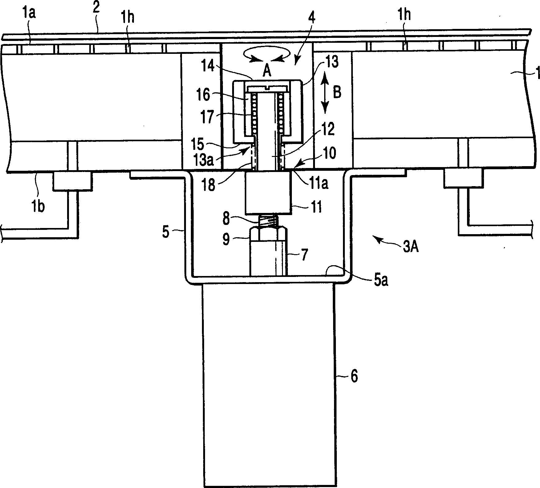
[0016] figure 1 It is an overall configuration diagram of the first substrate floating device. On the surface 1a of the floating table 1, for example, a plurality of air injection holes 1h are regularly provided, and the air injection holes 1h are used for blowing out air at a certain air pressure. In this floating table 1, the glass substrate 2 is placed on the surface 1a of the table, and air is injected from each air injection hole 1h to form an air layer between the surface 1a of the floating table 1 and the glass substrate 2, so that an air layer is formed between the surface 1a of the floating table 1 and the glass substrate 2. The glass substrate 1 floats on the surface 1 a of the float table 1 . In addition, the float table 1 is not limited to the air float method, and the glass substrate 2 may be floated from the table surface ...


PUM


Abstract

In the present invention, in the state where the substrate (2) is floating, the contact member (13) provided on the front end of the support member (10) is raised by using the lifting mechanism (6), so that the contact member (13) contacts the substrate (2). ), thereby restricting the movement of the floating substrate (2).

Description

technical field [0001] The present invention relates to a substrate floating device for floating a glass substrate used in a flat panel display (FPD) such as a liquid crystal display (LCD). Background technique [0002] For example, when inspecting an LCD glass substrate, it is necessary to align the glass substrate to a reference position. For example, Japanese Patent Laid-Open No. 8-313815 discloses a glass substrate positioning device. In this positioning device, a holding table is placed on an XY table by means of a ball caster, the holding table is used for suction and holding a glass substrate, and the holding table is moved by the force of a pressing cylinder, and the glass substrate is moved. The side edges are crimped directly to each datum pin for alignment. [0003] As the size of the glass substrate increases, the size of the holding table and the XY stage for sucking and holding the glass substrate also increases. In particular, in the XY stage, in order to m...

Claims


Application Information

Patent Timeline
IPC IPC(8): B65G49/06B65G49/07H01L21/683H01L21/687
CPCH01L21/68778B65G49/064B65G49/065H01L21/6838B65G49/02B65G49/07
Inventor 冈平裕幸
Owner OLYMPUS CORP
Why Eureka
Try Eureka