
Automatic feeding apparatus for button sewing machine

An automatic feeding and buttoning machine technology, applied in the field of buttoning machines, can solve problems such as damage, unstable feeding, poor adjustment ability, etc., and achieve the effect of preventing mutual interference

Pending Publication Date: 2018-11-30
WENZHOU ZHONGKE AUTOMATION EQUIP
View PDF10 Cites 5 Cited by
  • Summary
  • Abstract
  • Description
  • Claims
  • Application Information

AI Technical Summary

Problems solved by technology

[0002] The existing feeding devices of button sewing machines all have the problem of unstable feeding. At the beginning and end of feeding, the workpiece jumps due to the action of inertia, resulting in inaccurate button positions and even standing up buttons, which not only leads to The reduction of production rate and the quality of finished products will also lead to serious wear and tear of the machine; and the existing button sewing machine needs to replace a large number of parts for buttons of different sizes, and even needs to change equipment, with low tolerance and poor adjustment ability

Method used


Image

  • Automatic feeding apparatus for button sewing machine
  • Automatic feeding apparatus for button sewing machine
  • Automatic feeding apparatus for button sewing machine

Examples


Embodiment 1

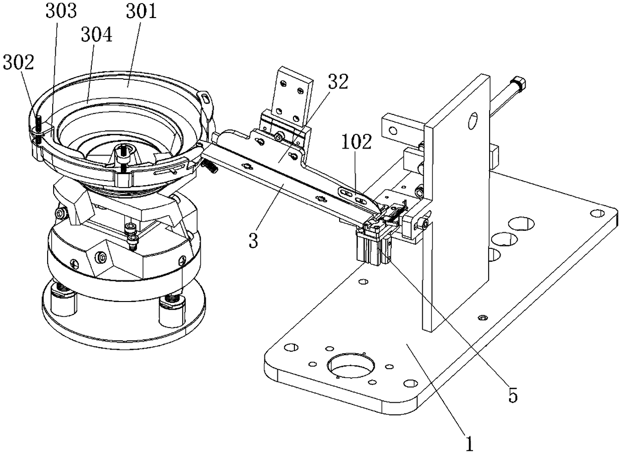
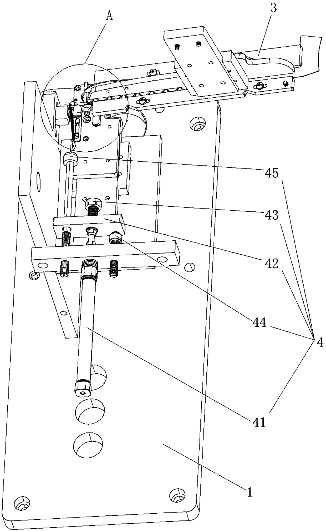
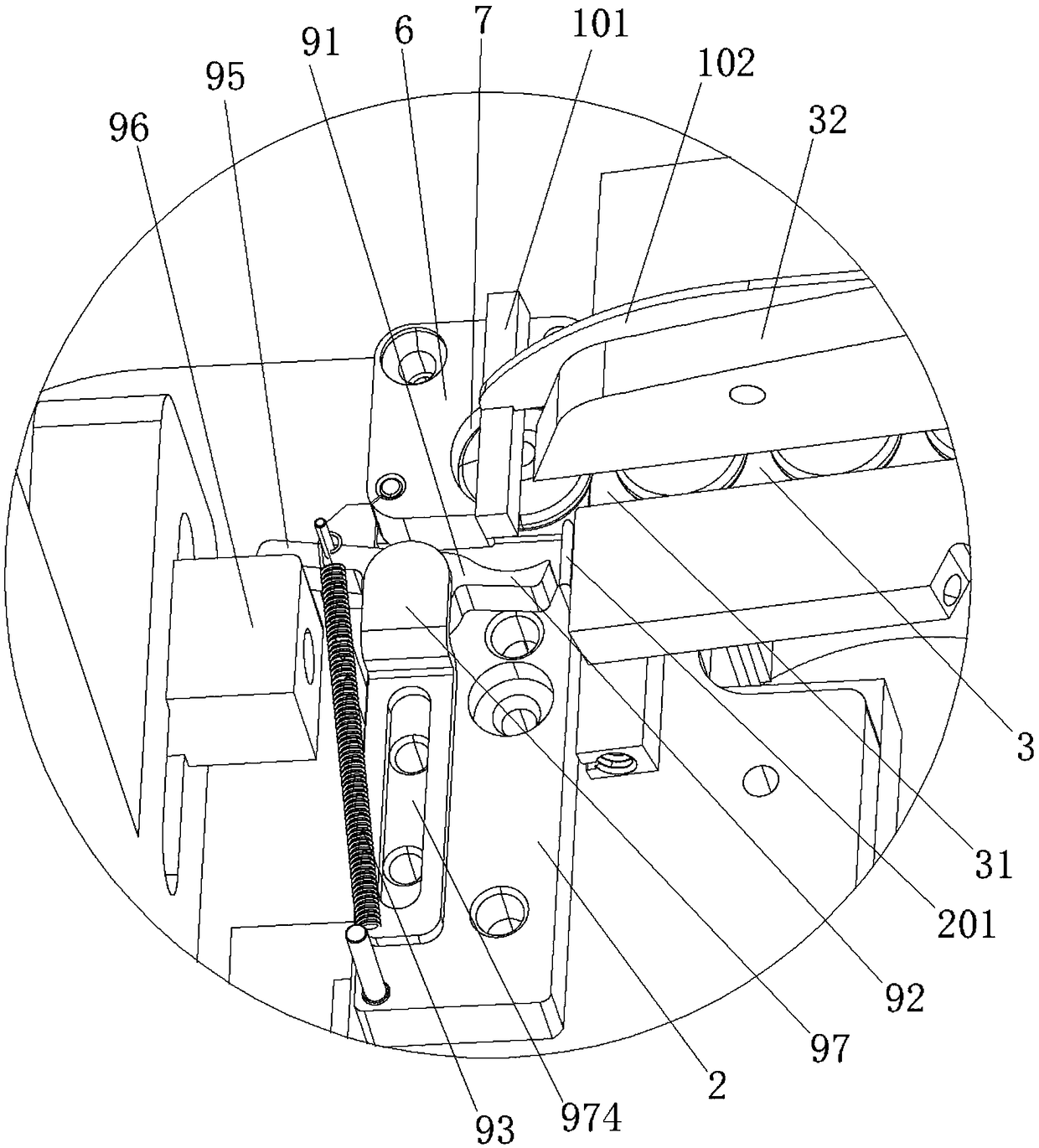
[0048] An automatic feeding device for a button sewing machine, comprising a frame 1, a feeding seat 2, a feeding track 3, a feeding seat pushing mechanism 4 for driving the feeding seat to reciprocate, and an upper cylinder 5, and the feeding seat 2 is provided with The positioning part 6 is formed with a positioning groove 7 on the positioning part 6, and the positioning groove 7 of the positioning part is provided with a workpiece anti-flying pressure strip 101, and the positioning groove 7 is provided with a feeding gap 8, and the side of the feeding gap is provided with The workpiece side clamping mechanism, the workpiece anti-flying pressure strip gives the workpiece pressure from top to bottom, and the workpiece side clamping mechanism gives the workpiece a radial pressing force, so that the workpiece is tightly attached to the side wall of the positioning groove 7, and the upper The top cylinder 5 is arranged below the positioning member, and the piston rod of the top c...

Embodiment 2

[0062] This embodiment is basically the same as Embodiment 1, the difference is that the workpiece longitudinal stabilization mechanism is an air blowing device arranged above the positioning groove, and the air blowing device blows air downwards to give the workpiece a downward force to prevent the workpiece from beat.

Embodiment 3

[0064] This embodiment is basically the same as Embodiment 1, the difference is that the workpiece longitudinal stabilization mechanism is a pressing plate arranged on the feeding seat, and the entire pressing plate covers the feeding seat. At this time, the depth of the positioning groove in the positioning member is basically the same as The thickness of the workpiece is the same, so that the effect of longitudinal stability can be achieved.


PUM


Abstract

The invention belongs to the field of button sewing machines, in particular to a novel automatic feeding apparatus for a button sewing machine. The apparatus comprises a frame, a feeding seat, a material loading track, a driving seat pushing mechanism and a lifting cylinder. The driving seat pushing mechanism drives the feeding seat to perform reciprocating motion. A positioning part is installedon the feeding seat. A positioning groove is formed in the positioning part. A workpiece anti-flying press strip is arranged in the positioning groove of the positioning part. A feeding gap is arranged in the positioning groove. The side surface of the feeding gap is equipped with a workpiece side buckle-clamping mechanism. The lifting cylinder is mounted below the positioning part. A position rodof the lifting cylinder corresponds to the center of the positioning groove. The novel automatic feeding apparatus for the button sewing machine has the following advantages: the apparatus is simplein structure and stable in feeding operation and can suitable for all kinds of differently-sized buttons; and the apparatus is also convenient to adjust.

Description

technical field [0001] The invention belongs to the field of button sewing machines, in particular to a novel automatic feeding device for button sewing machines. Background technique [0002] The existing feeding devices of button sewing machines all have the problem of unstable feeding. At the beginning and end of feeding, the workpiece jumps due to the action of inertia, resulting in inaccurate button positions and even standing up buttons, which not only leads to The reduction of the rate and the quality of the finished product will also lead to serious wear and tear on the machine; and the existing button sewing machine needs to replace a large number of parts for buttons of different sizes, and even needs to change the equipment, which has low tolerance and poor adjustment ability. Contents of the invention [0003] The purpose of the present invention is to provide a new type of automatic feeding device for button sewing machines with simple structure, stable feedin...

Claims


Application Information

Patent Timeline
Patent Type & Authority Applications(China)
IPC IPC(8): D05B3/22
CPCD05B3/22
Inventor 吴圣明
Owner WENZHOU ZHONGKE AUTOMATION EQUIP
Learn More