
Multilayer link plate type highly viscous fluid filtering machine

A filter and fluid technology, which is applied in the fields of filtration and separation, separation methods, chemical instruments and methods, etc., can solve the problems of high price and achieve the effect of cost saving

Inactive Publication Date: 2005-11-23
王克明
View PDF0 Cites 1 Cited by
  • Summary
  • Abstract
  • Description
  • Claims
  • Application Information

AI Technical Summary

Problems solved by technology

But the price is expensive, the current market price is about 2 million yuan

Method used


Image

  • Multilayer link plate type highly viscous fluid filtering machine
  • Multilayer link plate type highly viscous fluid filtering machine
  • Multilayer link plate type highly viscous fluid filtering machine

Examples


Embodiment Construction

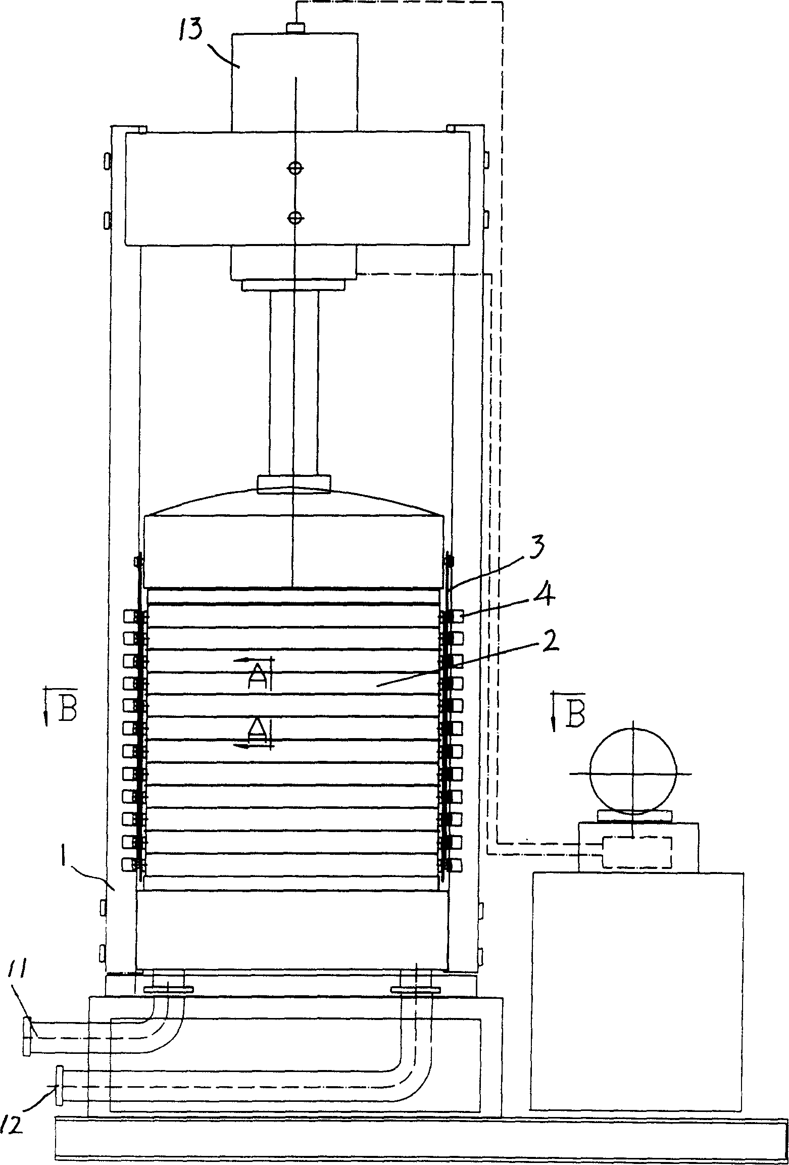
[0019] As shown in the figure, this embodiment includes a bracket 1, the bracket is provided with a liquid inlet 11 and a liquid outlet 12, several layers of filter plates 2 stacked on each other are arranged in the bracket 1, and a pressure cylinder 13 is arranged above the bracket 1 , the filter plate 2 is provided with a liquid inlet channel 21 and a liquid outlet channel 22, there are two liquid inlet channels 21 and two liquid outlet channels 22 on the filter plate 2, and the liquid inlet channel 21 is arranged on the filter plate 2 to form a diagonal line On the two corners of the distribution, the liquid outlet channel 22 is arranged on the other two opposite corners on the filter plate 2, and a guide tapered pipe 23 is provided above the liquid inlet channel 21 and the liquid outlet channel 22, and each filter plate 2 The liquid inlet channels 21 are superimposed on each other and connected to the liquid inlet 11 on the support 1, the liquid outlet channels 22 on each f...


PUM


Abstract

This invention relates to a high-viscosity fluid filter, which comprises a frame, an inlet port and an outlet port set in the frame; inside the frame is arranged several layer of superimposing sieve plates, and the top of the frame is arranged a pressure cylinder; on each sieve plate is arranged the inlet channel and outlet channel, wherein the inlet channel is connected with the inlet port of the frame, the outlet channel is connected with the outlet port of the frame; the topping of the sieve plate is arranged the filter cloth, and the lower of the filter cloth is arranged the supporting web who has a outlet pipe in the top, and the outlet pipe is connected with the outlet channel; the lower of the sieve plate is arranged on the inlet pipe connected with the inlet channel.

Description

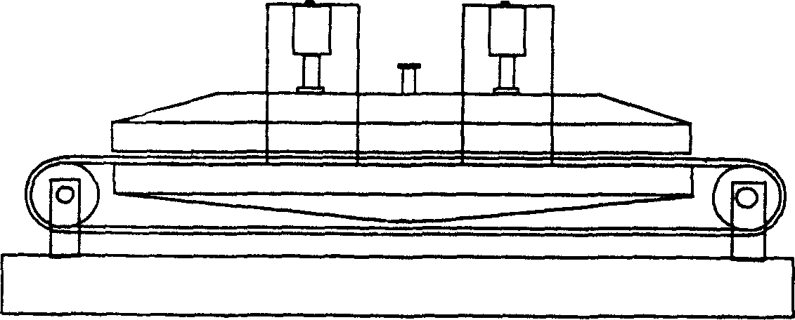
Technical field [0001] The invention relates to a high-viscosity fluid filter. Background technique [0002] The existing Japanese-made high-viscosity fluid filter is fully automatic equipment, such as figure 1 As shown, the equipment adopts a fully automatic crawler structure, and uses two oil cylinders to join the upper and lower 3 square meters of steel plate filter discs with extremely high surface precision. The pressure of each oil cylinder is 120 tons, which can ensure 30 tons per square meter. tons of filtration pressure. When working, the oil to be filtered enters from the oil injection hole and passes through a 6 mm diatomite filter layer at the lower steel plate to achieve the purpose of filtration. When it is necessary to clean the dirty diatomite filter layer, lift the oil cylinder, turn the crawler, and the diatomite will be transferred to the recovery container. In this way, a new filtering work can start again. The feature of this equipment is that the pr...

Claims


Application Information

Patent Timeline
Patent Type & Authority Applications(China)
IPC IPC(8): B01D25/12
Inventor 王克明
Owner 王克明
Learn More