Switch device

A technology of switchgear and conductor plate, applied in the direction of electric switches, electrical components, circuits, etc., can solve problems such as difficult to use, long depth and dimension

Inactive Publication Date: 2005-11-23
ALPS ALPINE CO LTD
View PDF1 Cites 4 Cited by
  • Summary
  • Abstract
  • Description
  • Claims
  • Application Information

AI Technical Summary

Problems solved by technology

[0013] However, in the structure of the above-mentioned conventional switchgear, the contact mechanism constituted by the fixed terminal 32 having the fixed contact 32a and the central terminal 33 movably supporting the conductor plate 38 fixed with the movable contact 39, due to the Since the sliding member 41 is arranged on the inner bottom surface of the casing 3 in the same direction as the pushing operation direction, the depth (inward dimension) is long, making it difficult to use it in a device with a limited depth such as a thin TV.

Method used


Image

  • Switch device
  • Switch device
  • Switch device

Examples


Embodiment Construction

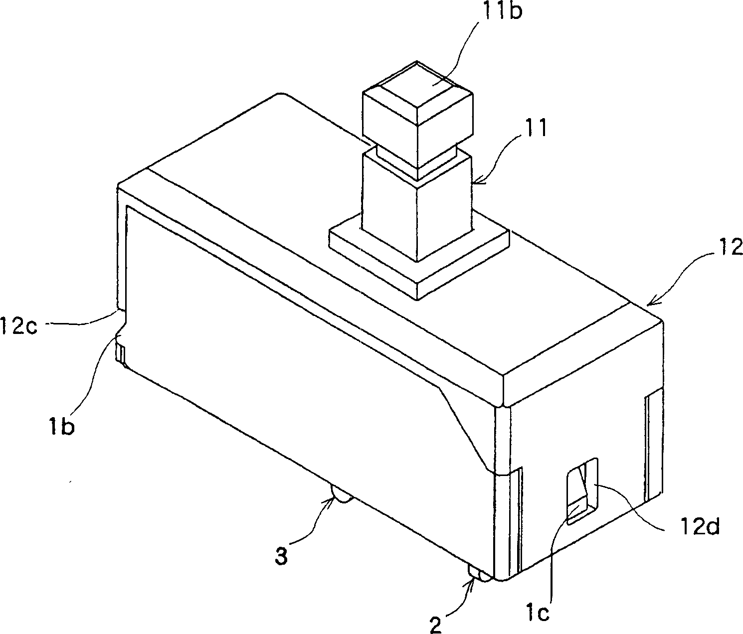
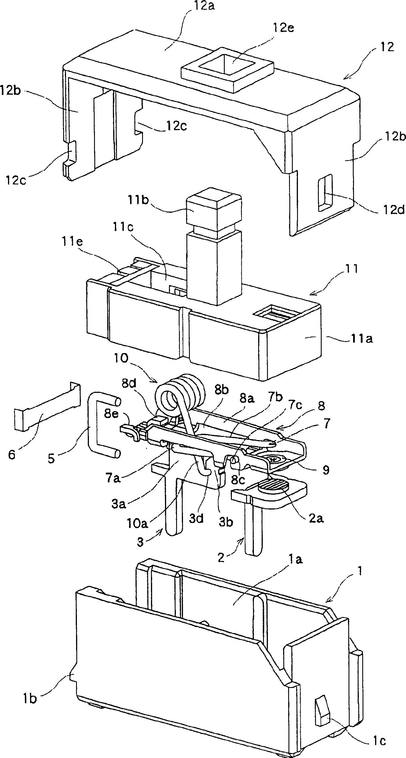
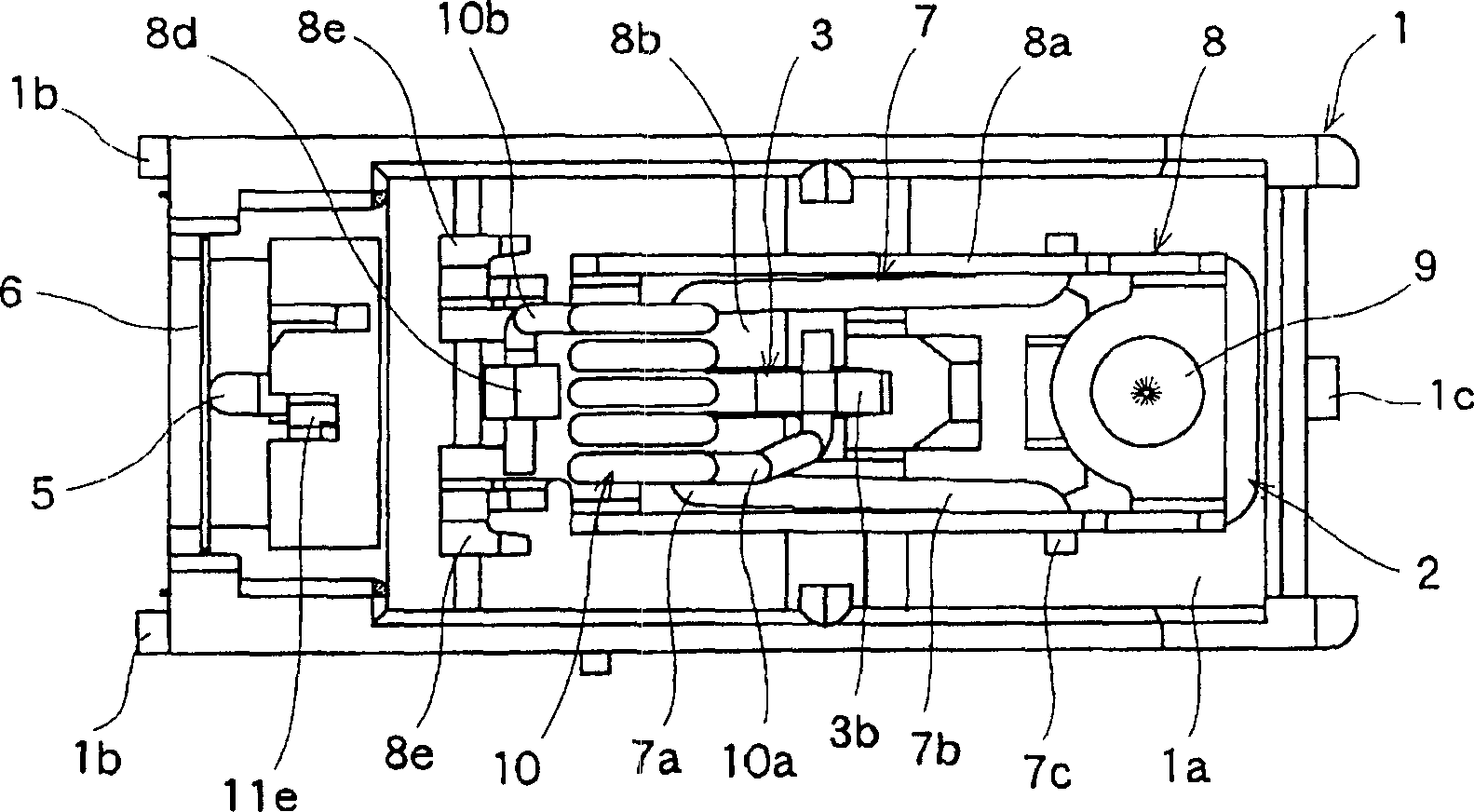
[0031] the following, Figure 1 to Figure 5 An embodiment of the switchgear of the present invention is shown. figure 1 is a perspective view of the switch device of the present invention, figure 2 is an exploded perspective view of the switchgear of the present invention, image 3It is a plan view of main parts showing the contact mechanism part of the switchgear of the present invention, Figure 4 It is an operation explanatory diagram showing the off state of the switch device of the present invention, Figure 5 It is an operation explanatory diagram showing the conduction state of the switching device of the present invention.

[0032] In the figure, the casing 1 is made of an insulating material such as synthetic resin, and is formed in a box shape with its upper surface and one side open. An accommodating portion 1a is formed in the opening of the housing 1, and fixed terminals 2 made of conductive metal plates having fixed contacts 2a on the upper surface are resp...


PUM


Abstract

The objective ia to provide a switching arrangement the depth dimension of which can be shortened, and which can be used for a thin type set having a restricted depth. This switching arrangement is equipped with a stationary terminal, a conductor plate having a movable contact moved into and out of contact with a stationary contact provided on the stationary terminal, a center terminal which movably supports the conductor plate and is provided side by side with the stationary terminal on the inner bottom face of a case, a support arm one end of which is locked by the conductor plate and the other end of which is locked by the center terminal, an elastic member locked between the conductor plate and the center terminal to movably energize the conductor plate, an operating member to force the movable contact into and out of contact with the stationary contact by driving the conductor plate, and locking mechanisms, to lock the operating member at a pushing position. The stationary terminal and the center terminal are provided side by side in the direction perpendicular to the pushing direction of the operating member, and the conductor plate is made movable perpendicularly to the direction in which the conductor plate and the center terminal are provided side by side, by pushing the operating member.

Description

technical field [0001] The present invention relates to a switch device, and in particular to a structure of a switch device used as a power switch of a thin digital device such as a liquid crystal television. Background technique [0002] As a structure of a switch device used as a conventional power switch, it is known to have a pushing operation using an inclined surface formed by an inclined surface provided on the operating member by following the pushing operation of the operating member (sliding member) in the lateral direction. A switch device that drives a conductor plate with a movable contact that is in contact with and separate from a fixed contact provided on the inner bottom surface of the housing in a longitudinal direction perpendicular to the pressing direction of the operating member, and performs on / off of the contact ( For example, refer to Patent Document 1). [0003] Hereinafter, the configuration of a conventional switch device will be described with ...

Claims


Application Information

Patent Timeline
IPC IPC(8): H01H13/30H01H13/56
Inventor 森俊晴
Owner ALPS ALPINE CO LTD
Why Eureka
Try Eureka