Design method for push rod of hydraulic support

A design method and technology of hydraulic support, applied in pillars/supports, mining equipment, earthwork drilling and mining, etc., can solve the problems of unsuitable support, hydraulic support design, manufacture, and assembly inconvenience, so as to improve design work efficiency and facilitate maintenance , reduce the effect of the design

Inactive Publication Date: 2005-11-30
ZHENGZHOU COAL MINING MACHINERY GRP
View PDF0 Cites 1 Cited by
  • Summary
  • Abstract
  • Description
  • Claims
  • Application Information

AI Technical Summary

Problems solved by technology

The structural form of the push rod depends on the form of the push jack used, and the length of the push rod is affected by many uncertain factors such as the installation position on the base. If the size of the push rod is fixed, it cannot be applied to all brackets, which is It causes a lot of inconvenience to the design

Method used


Image

  • Design method for push rod of hydraulic support
  • Design method for push rod of hydraulic support
  • Design method for push rod of hydraulic support

Examples


Embodiment Construction

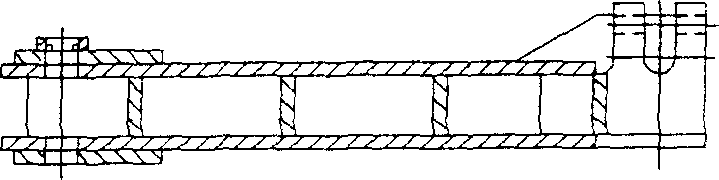
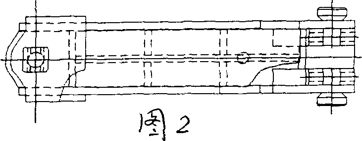
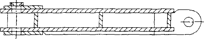
[0019] As shown in the figure, the design method of the hydraulic support push rod of the present invention is to fix the cross-sectional area size of the push rod which is difficult to design through strength calculation, and divide the easy-to-achieve length changes into series, specifically The design steps are as follows:

[0020] The first step is to divide the putter into three structural forms: short putter, integral long putter, and split long putter;

[0021] The second step is to fix the cross-sectional area size of the push rod under the condition of meeting the strength requirements for the short push rod and the overall long push rod according to the bore diameters of the push jacks connected to them; the length is within the specified size range A series is formed within a certain interval; the change in the length of the components corresponding to each length in the series is listed in the component chart one by one in the form of a list; the change size of eac...


PUM


Abstract

This invention discloses a method for designing hydraulic support ram, which comprises the following steps: a) dividing the ram to short ram, integral long ram and split long ram; b) for short ram and integral long ram, ascertaining their cross-sectional area size according to the bore of push jack connecting to said rams; the length within given size range form series with a certain interval; the change of elements length which are corresponding to each length will be listed in the component diagram, and each varied size is corresponding to a certain letter; c) for split long ram, fixing the size of rear ram, varying the size of front ram to change the total length of split long ram; wherein the front ram is designed according to said short ram in step b.

Description

technical field [0001] The invention relates to a hydraulic support for supporting equipment in a fully mechanized coal mining face, in particular to a design method for a push rod of the hydraulic support. Background technique [0002] The push rod in the hydraulic support is located in the middle gap of the base, placed on the bottom plate, and connected with the moving jack and the connecting head through the pin shaft to form a moving device, so as to realize the forward movement of the support itself and the conveyor. [0003] Due to the complex geological conditions, there are many structural forms of hydraulic supports, which are affected by many uncertain factors, resulting in various forms of push rods. According to the form, the push rod can be divided into two categories: long push rod and short push rod, which are generally box-shaped structural parts welded by steel plates. The long push rod is further divided into an integral box-type long push rod and a split...

Claims


Application Information

Patent Timeline
IPC IPC(8): E21D15/48
Inventor 焦承尧高有进刘学丽杨惠敏穆燕英史艳冰
Owner ZHENGZHOU COAL MINING MACHINERY GRP
Why Eureka
Try Eureka