
Transformer

A technology of transformers and iron cores, which is applied in the direction of transformers, fixed transformers, transformer/inductor cores, etc., and can solve the problems of the difference in length between the inner and outer magnetic circuits of iron core materials, high magnetic flux density, and reduced magnetic flux density.

Inactive Publication Date: 2005-11-30
HITACHI IND EQUIP SYST CO LTD
View PDF2 Cites 7 Cited by
  • Summary
  • Abstract
  • Description
  • Claims
  • Application Information

AI Technical Summary

Problems solved by technology

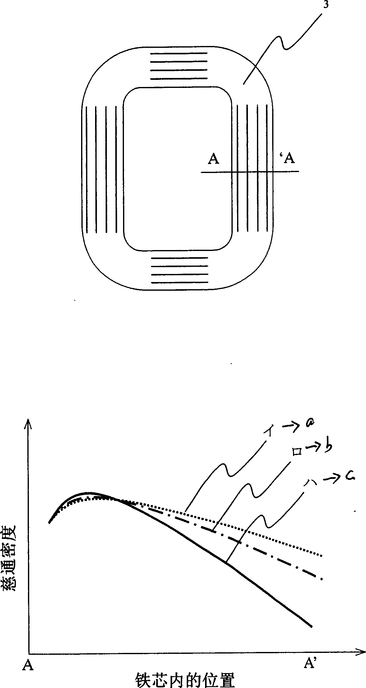
[0003] In the existing wound core, due to the difference in the length of the inner and outer magnetic paths of the core material, the magnetic flux density is high inside the core, and the magnetic flux density decreases as it goes to the outer periphery.
Due to this, the deformation of the magnetic flux waveform due to the concentration of magnetic flux occurs, and abnormal loss occurs, which inevitably deteriorates the characteristics.

Method used


Image

  • Transformer
  • Transformer
  • Transformer

Examples


Embodiment Construction

[0022] Hereinafter, preferred embodiments of the present invention will be described with reference to the drawings.

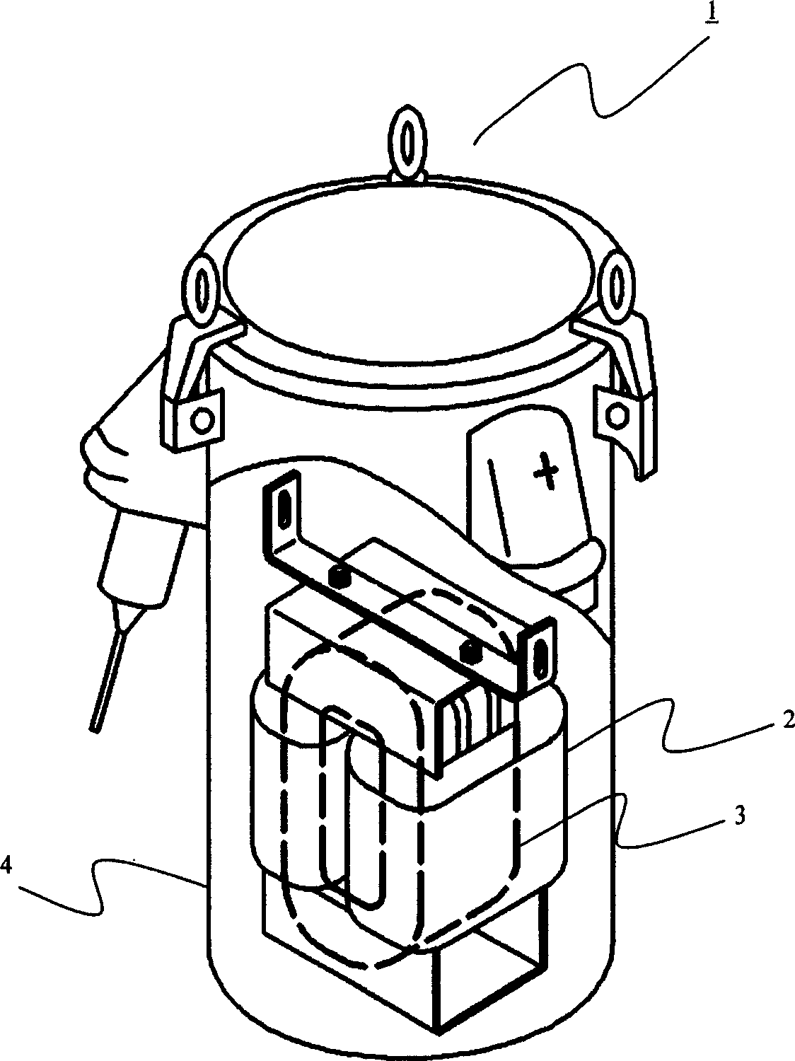
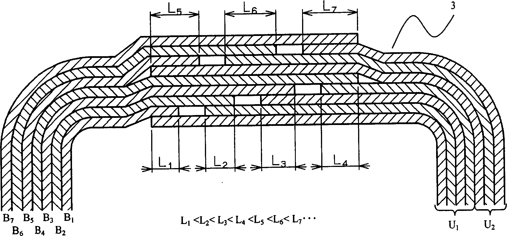
[0023] Figure 1~3 It is an explanatory diagram of the first embodiment of the present invention. figure 1 It is a diagram of a structural example of a transformer as a first embodiment of the present invention. figure 2 for figure 1 Structural diagram of the junction cross-section of the iron core used in the transformer. image 3 It is an explanatory diagram of the magnetic flux distribution in the iron core.

[0024] exist figure 1 Among them, 1 is a transformer, 2 is an excitation coil forming an electric circuit, 3 is a wound core forming a magnetic circuit, and 4 is a container for mechanically protecting the transformer. Iron core 3 is, for example, 0.02×10m -3 ~0.60×10 -3 The plate-shaped magnetic materials of about m are stacked in multiple layers, and are stacked into a ring shape. The two ends of the laminated plate-shaped magnetic material...


PUM


Abstract

There is provided a joint structure of a wound iron core in which iron core characteristics can be enhanced by improving the distribution of magnetic flux within an iron core. A wound iron core is formed to provide a joining structure or a butt joining structure and a lap joining structure disposed in an appropriate arrangement in which the a margin of overlapping is more increased as being closer to an outer periphery from an inner periphery of the iron core, taking a distribution of magnetic flux density within the iron core into consideration.

Description

technical field [0001] The present invention relates to the structure of the transformer, in particular to the structure of the iron core. Background technique [0002] As prior arts related to the present invention, there are, for example, JP-A-6-84656 and JP-A-9-7849. Japanese Unexamined Patent Publication No. 6-84656 describes a technique related to a method of manufacturing a wound iron core using an amorphous alloy thin strip and a joint structure. JP-A-9-7849 describes a technique related to a manufacturing method and a joint structure of an iron core having an overlapping joint as a basic joint structure in a wound iron core using an amorphous alloy thin strip. [0003] In the conventional wound core, the magnetic flux density is high inside the core due to the difference in the length of the inner and outer magnetic paths of the core material, and the magnetic flux density decreases toward the outer periphery. Because of this, the magnetic flux waveform is deformed...

Claims


Application Information

Patent Timeline
IPC IPC(8): H01F27/25H01F27/24H01F30/00H01F30/12
Inventor 山下晃司松田洋二西山和男细川正雄福井和元山口英正本间徹远藤博之篠原诚
Owner HITACHI IND EQUIP SYST CO LTD
Learn More