
Analyzing tool and device

An analysis tool and analysis device technology, which is applied in the direction of chemical analysis, analysis materials, and measurement devices using microanalysis, which can solve the problems of increased manufacturing costs, increased operating costs, and complicated devices.

Inactive Publication Date: 2005-12-07
ARKRAY INC
View PDF2 Cites 12 Cited by
  • Summary
  • Abstract
  • Description
  • Claims
  • Application Information

AI Technical Summary

Problems solved by technology

Therefore, the device for analyzing the sample liquid using the analysis tool is complicated, the manufacturing cost increases, and the running cost increases because the analysis tool needs to be rotated at a high speed.

Method used


Image

  • Analyzing tool and device
  • Analyzing tool and device
  • Analyzing tool and device

Examples


Embodiment Construction

[0033] Next, first to third embodiments of the present invention will be described with reference to the drawings.

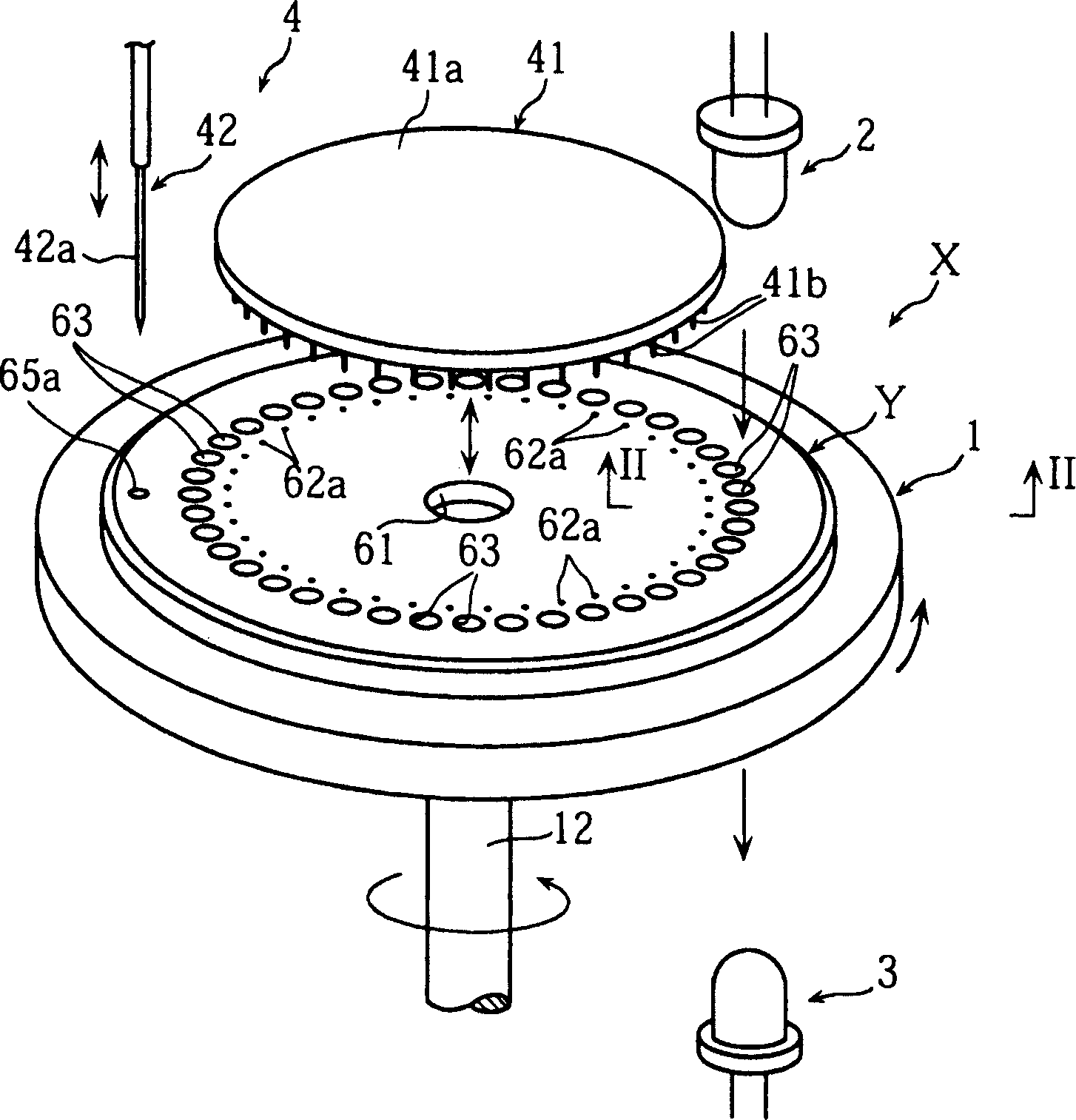
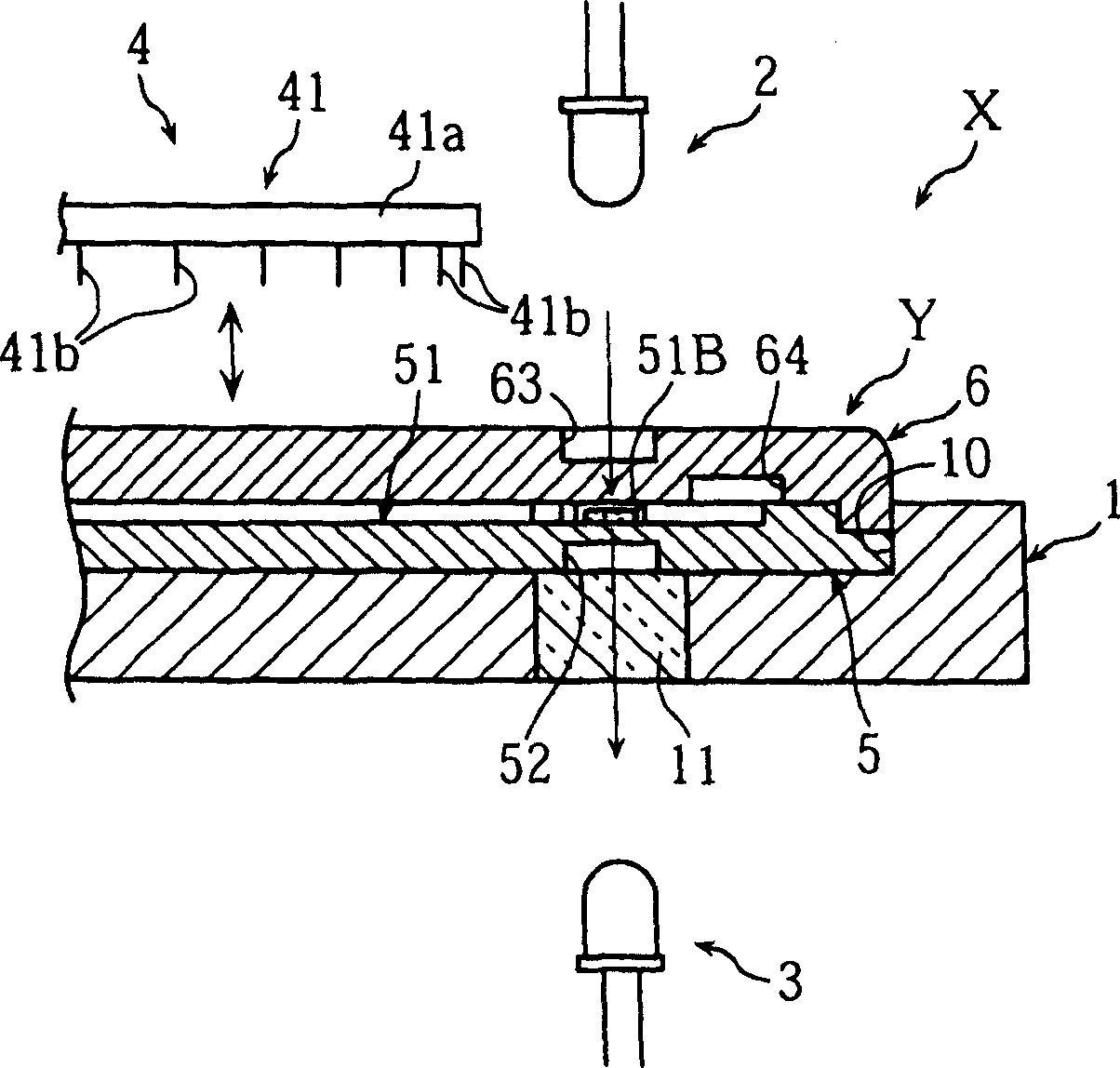
[0034] First, refer to Figure 1 ~ Figure 1 0 The first embodiment of the present invention will be described.

[0035] figure 1 as well as figure 2 The analysis device X shown is a device equipped with a microdevice Y as an analysis tool for sample liquid analysis, and includes a mounting part 1 for mounting the microdevice Y, a light source part 2, a light receiving part 3, and an opening mechanism 4.

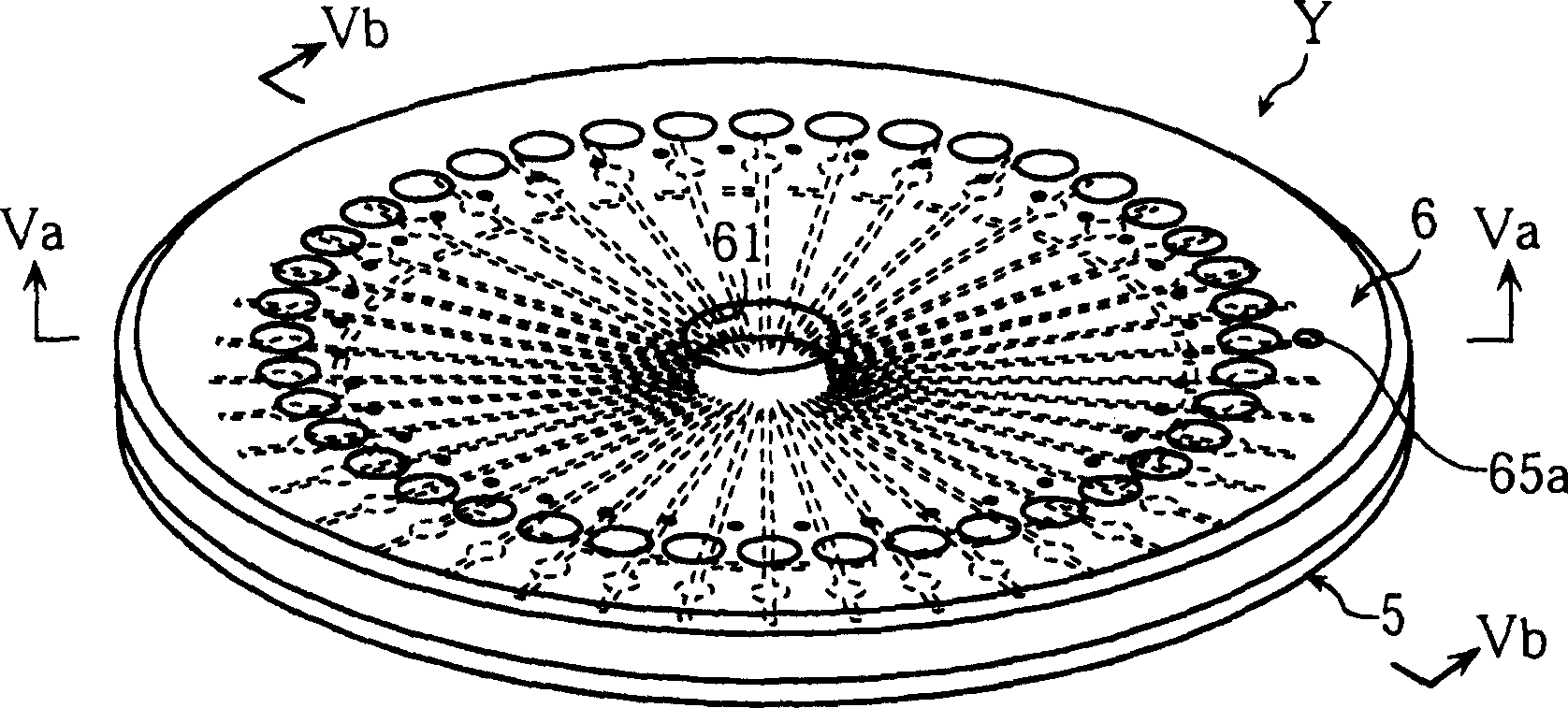
[0036] image 3 The microdevice Y shown in FIG. 5 is a device for providing a reaction field, and has a substrate 5 , a cover 6 , a bonding layer 7 and a separation membrane 8 .

[0037] The substrate 5 is formed in a transparent disk shape, and has a stepped shape at the peripheral edge. Such as Figure 5A as well as Image 6 As shown, the substrate 5 has a liquid receiving portion 50 provided in the center, a plurality of flow channels 51 communicat...


PUM


Abstract

A tool and device for analyzing a specific component in a sample liquid. An analyzing tool (Y) has a liquid-introducing opening (61) provided at the central part of the tool and plural flow passages (51) that are penetrated to the liquid-introducing opening (61) and allow the sample liquid introduced from the liquid-introducing opening (61) to flow from the central part toward a peripheral edge portion using a capillary phenomenon. Each of the flow passages (51) extends, for example, linearly from the central part to the peripheral edge portion, and the plural flow passages (51) are radially arranged.

Description

technical field [0001] The present invention relates to an analysis tool and an analysis device used for analyzing a sample liquid. Background technique [0002] As an analysis method of the sample liquid, for example, there is a method of optically analyzing the reaction liquid when the sample liquid and the reagent are reacted. When analyzing a sample liquid by this method, an analysis tool that provides a reaction field is used. An analysis tool has a plurality of flow paths so that a plurality of items can be analyzed using one sample liquid, or the same item can be analyzed with a plurality of sample liquids. [0003] For analytical instruments with multiple flow paths, such as Figure 13A as well as Figure 13B As shown, it is formed in a rectangular shape, and the main parts of the plurality of channels 90A, 90B are arranged parallel to each other. On the other hand, there is also an analytical tool in which a plurality of channels are arranged radially (for exampl...

Claims


Application Information

Patent Timeline
Patent Type & Authority Applications(China)
IPC IPC(8): G01N31/20B01L3/00G01N1/00G01N21/03G01N21/25G01N33/48G01N35/00G01N35/02G01N35/10G01N37/00
CPCG01N2021/0346B01L2400/0409B01L2300/0864G01N35/10G01N35/025B01L2300/1872G01N2035/00158B01L2300/0803B01L2400/0406G01N35/00069G01N21/253B01L3/5027
Inventor 田口尊之北村茂野田雄一原田敏彦
Owner ARKRAY INC
Learn More