Suction head of vacuum cleaner

A technology for vacuum cleaners, dust, applied in the direction of vacuum cleaners, suction nozzles, household appliances, etc.

Inactive Publication Date: 2005-12-14
LG ELECTRONICS INC
View PDF0 Cites 14 Cited by
  • Summary
  • Abstract
  • Description
  • Claims
  • Application Information

AI Technical Summary

Problems solved by technology

Accordingly, the bristles 12 of the brush 13 sweep the floor in a

Method used


Image

  • Suction head of vacuum cleaner
  • Suction head of vacuum cleaner
  • Suction head of vacuum cleaner

Examples


Embodiment Construction

[0020] Reference will now be made in detail to the preferred embodiments of the present invention, examples of which are illustrated in the accompanying drawings.

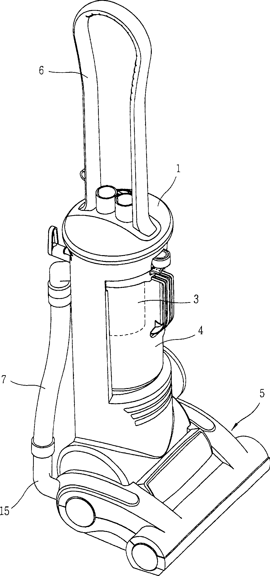
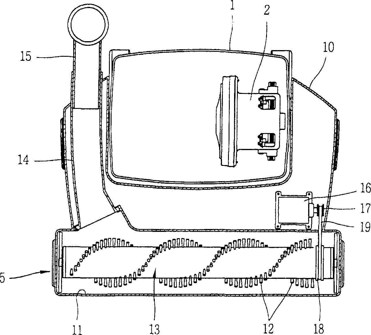
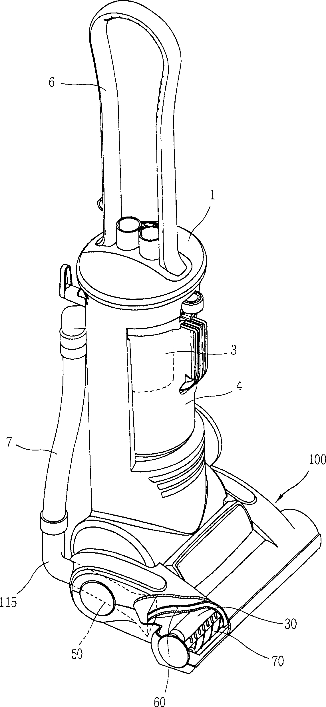
[0021] Such as image 3 with 4 As shown, the upright vacuum cleaner according to the present invention includes: a main body 1 with accommodating space therein; a handle 6 installed on the upper side of the main body 1; a fan motor 2 installed on the main body 1 and generating suction; arranged on the suction side of the fan motor 2 And the filter 3 that filters dust; The dust chamber 4 that is used to accommodate the filter 3 and the dust filtered by the filter 3; Operate to inhale external dust.

[0022] The suction head 100 includes: a housing 110 provided with a suction port 20 having a structure open to the floor; a cylindrical main brush 30 rotatably mounted on the suction port 20, and arranged in the longitudinal direction of the main brush. A plurality of bristles 31; a main brush driving device 40 for r...


PUM


Abstract

A suction head of a vacuum cleaner, which includes: a casing with a suction port through which dust on the floor is sucked through the suction port by the operation of a fan motor; a main brush rotatably installed at the suction port, and A plurality of bristles are arranged in a direction; a main brush driving device for reciprocatingly rotating the main brush within a predetermined angle range; and an auxiliary brush rotatably installed on one side of the main brush and arranged in a longitudinal direction thereof Brush, used to supplement the operation of the main brush by rotation. Accordingly, the entire area occupied by the suction head can be evenly brushed, and the brushed dust can be smoothly sucked in.

Description

technical field [0001] The present invention relates to a vacuum cleaner head, and more particularly to a vacuum cleaner head capable of enhancing the cleaning function by providing an auxiliary brush for supplementing the operation of the brush to collect dust on the floor. Background technique [0002] Such as figure 1 with 2 As shown, the upright vacuum cleaner according to the conventional technology includes: a main body 1 having an accommodating space therein; a handle 6 installed on the upper side of the main body 1; a fan motor 2 installed on the main body 1 and generating suction; arranged on the suction side of the fan motor 2 And the filter 3 that filters dust; The dust chamber 4 that is used to accommodate the filter 3 and the dust filtered by the filter 3; Operate to inhale external dust. [0003] The suction head 5 comprises: a casing 10 provided with a suction port 11, which has a structure open to the floor; a suction pipe 14 for collecting dust sucked thr...

Claims


Application Information

Patent Timeline
IPC IPC(8): A47L9/02A47L9/04
CPCA47L9/0411A47L9/0483A47L9/02
Inventor 赵晟浩刘明根南泳硕
Owner LG ELECTRONICS INC
Why Eureka
Try Eureka