Image projection apparatus having cleaning function of air filter

a technology of air filter and cleaning function, which is applied in the field of image projection apparatus having a cleaning function of air filter, can solve the problems of increasing the output of the cooling fan, clogging of the air filter, and increasing noise, and achieves the effect of good cleaning function of the air filter

Inactive Publication Date: 2013-06-18
CANON KK
View PDF6 Cites 7 Cited by
  • Summary
  • Abstract
  • Description
  • Claims
  • Application Information

AI Technical Summary

Benefits of technology

[0009]The present invention provides an image projection apparatus that has a good cleaning function of an air filter without causing the addition of an air filter to an exhaust port or the increases of an output and a noise of a cooling fan.

Problems solved by technology

The clogging of the air filter caused by dusts may be generated by the use of the projector for a long time.
In this case, since the pressure difference is generated between the inside and the outside of the chassis, the cleaning air is inevitably suctioned from the outside of the chassis.
Moreover, in this projector, a flow path resistance of the air exhausted to the outside of the chassis via the exhaust port during the normal drive increases caused by providing the air filter in the exhaust port of the cooling air, and the necessity of increasing the output of the cooling fan is created or the noise is increased.

Method used


Image

  • Image projection apparatus having cleaning function of air filter
  • Image projection apparatus having cleaning function of air filter
  • Image projection apparatus having cleaning function of air filter

Examples


embodiment 1

[0020]Whole configuration of a projector

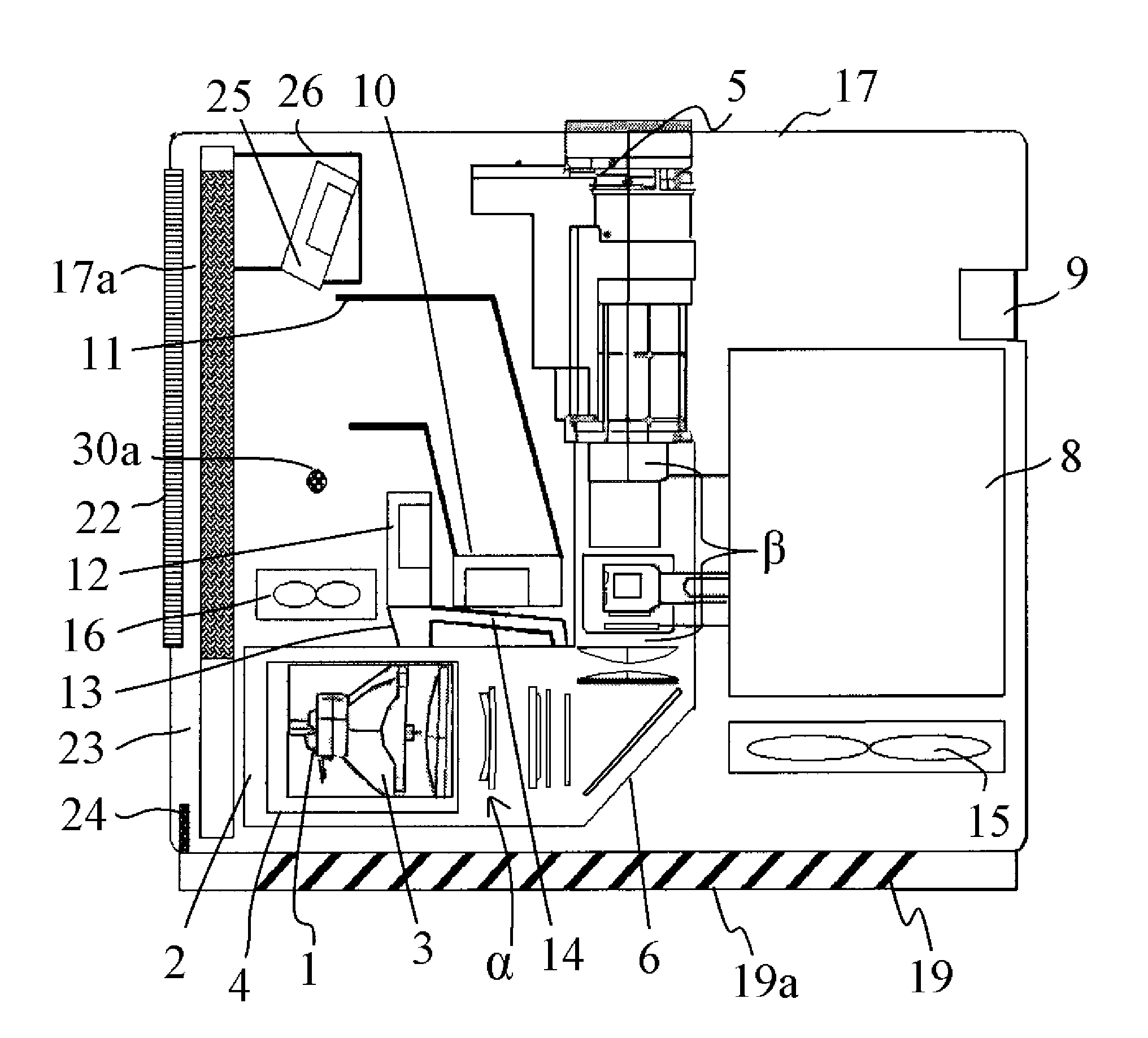
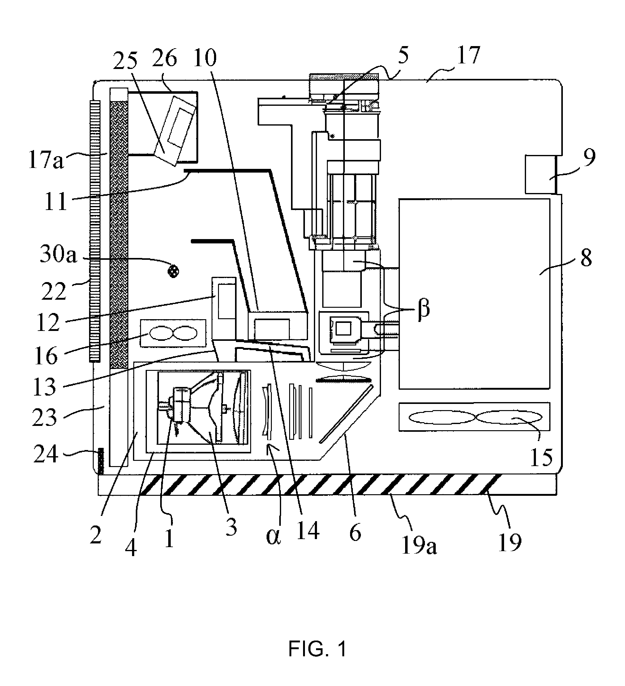
[0021]FIG. 1 illustrates a configuration of a liquid crystal projector (an image projection apparatus) that is Embodiment 1 of the present invention.

[0022]In FIG. 1, reference numeral 1 denotes a light source lamp (hereinafter, referred to simply as a lamp), and a high-pressure mercury discharge lamp is used in the embodiment. However, a discharge lamp such as a halogen lamp, a xenon lamp, or a metal halide lamp, other than the high-pressure mercury discharge lamp, may also be used as the lamp 1.

[0023]Reference numeral 2 denotes a lamp holder that holds the lamp 1 using a biasing force from a plurality of spring materials (not shown). Reference numeral 3 denotes an explosion-proof convex lens, and reference numeral 4 denotes a lamp unit that is constituted by the lamp 1, the lamp holder 2, the explosion-proof convex lens 3, and the like.

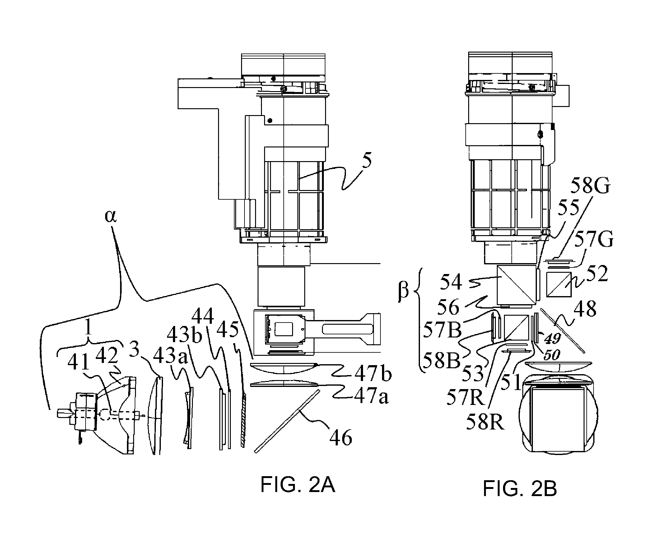
[0024]Reference character α denotes an illumination optical system that converts luminous flux from the lamp...

embodiment 2

[0074]FIG. 5 illustrates a configuration of a liquid crystal projector that is Embodiment 2 of the present invention. The projector of the embodiment has a structure of dividing the cooling inlet port 17a formed as one member for both the cooling airflow path A and the cooling airflow path B in Embodiment 1 (FIG. 3) into an inlet port 117a for the cooling airflow path A and an inlet port 117b for the cooling airflow path B. Specifically, a wall portion of the RGB duct 11 is extended up to the cooling inlet port 17a to use the wall portion as a partition to divide the inlet port 117a for the cooling airflow path A and the inlet port 117b for the cooling airflow path B. In other words, the embodiment has the structure that leads the cooling air discharged from the cooling fan 25 to the area (the inlet port 117b for the cooling airflow path B) where the cooling air that cools the color separation / synthesis optical system β provided with the liquid crystal panel that is an optical modul...

embodiment 3

[0079]FIG. 6 and FIG. 7 illustrate a configuration of a liquid crystal projector that is Embodiment 3 of the present invention. The embodiment is different from Embodiment 1 in that an air guide louver (an air guide member) 28 is added and that the cooling fan 25 is disposed in parallel to the cooling inlet port 17 (so that the discharged port faces a direction in which the cooling inlet port 17 extends), and other configurations are the same as those of Embodiment 1.

[0080]In FIG. 6, a flow path of the air (cleaning air) that flows by the rotation of the cleaning fan 25 during the cleaning operation of the air filter 22 is indicated as a cleaning airflow path E. Similarly to Embodiment 1, during the cleaning operation, the operations of all the optical cooling fan 10, the first lamp cooling fan 12, and the second lamp cooling fan 16, and the power supply exhaust fan 15 stop.

[0081]The air guide louver 28 has a shape that is illustrated as an enlarged view in FIG. 7. In other words, t...


PUM


Abstract

An image projection apparatus includes cooling fans 10, 12, and 16 provided inside a chassis 17 and configured to take in cooling air from a cooling inlet port 17a formed in the chassis, an air filter 22 that covers the cooling inlet port, an exhaust port 19a formed in the chassis and configured to exhaust the cooling air from an inside to an outside of the chassis, and a cleaning fan 25 provided inside the chassis and configured to take in cleaning air from a cleaning inlet port 17b formed in the chassis separately from the exhaust port. The image projection apparatus exhausts the cleaning air discharged from the cleaning fan, from the inside to the outside of the chassis via the cooling inlet port and the air filter.

Description

BACKGROUND OF THE INVENTION[0001]1. Field of the Invention[0002]The present invention relates to an image projection apparatus such as a liquid crystal projector, and more particularly to an image projection apparatus having a cleaning function of an air filter.[0003]2. Description of the Related Art[0004]The image projection apparatus (Hereinafter, referred to as a projector) as described above is provided with a cooling fan in a chassis in order to cool a light source such as a lamp or an optical modulation element such as a liquid crystal panel. An inlet port that is formed in the chassis to take in outside air as cooling air by the cooling fan is covered with a dust-proof air filter.[0005]The clogging of the air filter caused by dusts may be generated by the use of the projector for a long time. Therefore, the air filter needs to be cleaned regularly or if necessary. Japanese Patent Laid-Open No. 2004-064010 discloses a projector that cleans an air filter by rotating a cooling f...

Claims


Application Information

Patent Timeline
Patent Type & Authority Patents(United States)
IPC IPC(8): G03B21/18G03B21/26G03B21/14G03B21/00G03B21/22
CPCG03B21/16
Inventor NAKASHITA, DAISUKE
Owner CANON KK
Why Eureka
Try Eureka