
Staple gun with light source

A nailing machine and light source technology, applied in the field of nailing machines, can solve problems such as insufficient light, insufficient use of nailing machines, and inability of users to use nailing machines accurately, so as to achieve reliable and accurate nailing Effect

Inactive Publication Date: 2005-12-14
ROBERT BOSCH GMBH
View PDF0 Cites 2 Cited by
  • Summary
  • Abstract
  • Description
  • Claims
  • Application Information

AI Technical Summary

Problems solved by technology

[0003] A disadvantage of the known nailing machines is that the nailing machine can only be used insufficiently in some situations involving poor lighting conditions
In fact in this case the user cannot use the known nailing machine accurately because there is not enough light for him to see exactly where the nailing machine is placed

Method used


Image

  • Staple gun with light source

Examples


Embodiment Construction

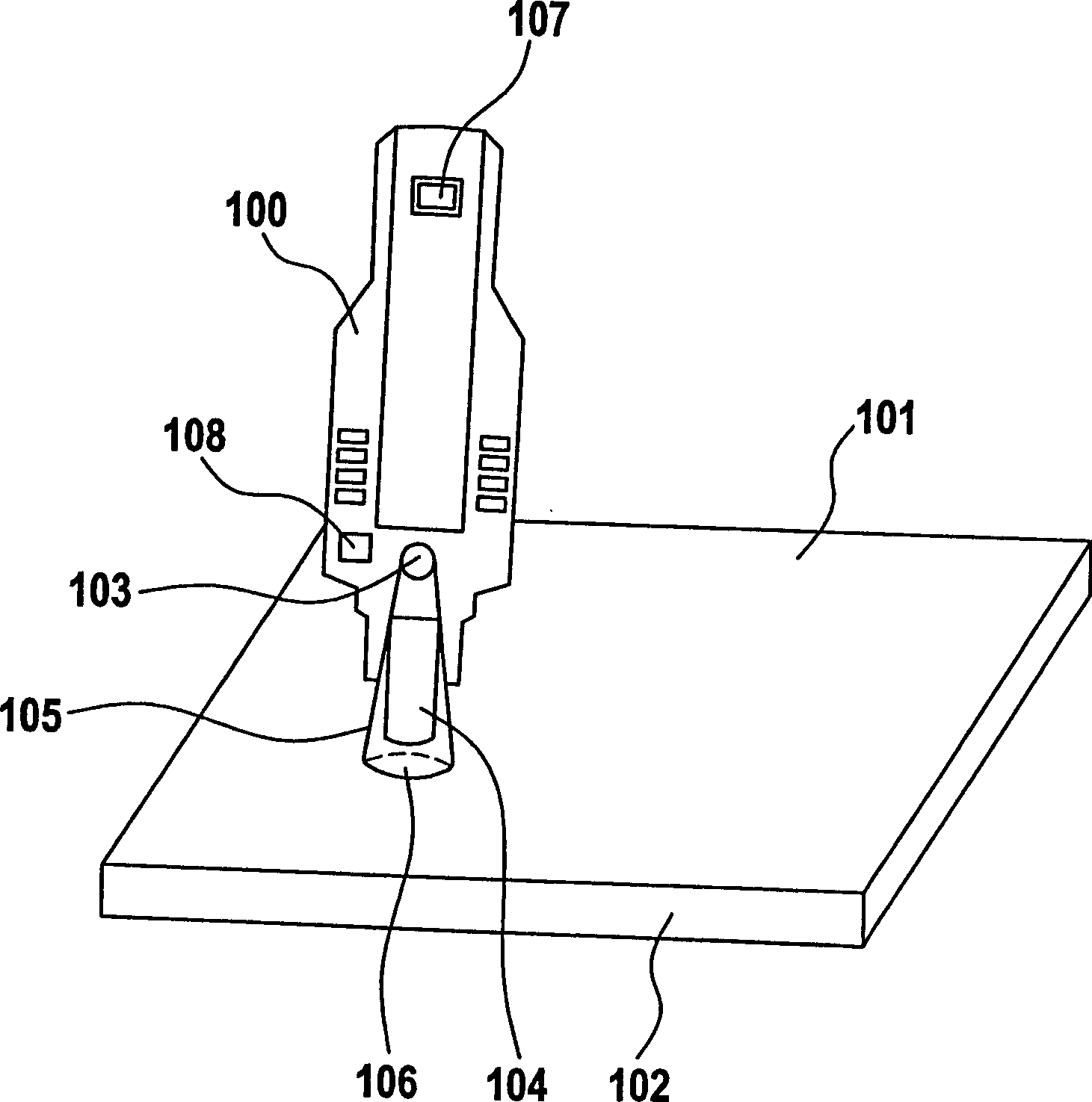
[0014] the only attached figure 1 A nailing machine 100 is shown which is placed on a surface 101 of a material 102 to be stapled. The stapler 100 has a light source 103 designed as a light emitting diode (LED). Underneath the LEDs 103 is a stapler boss 104 of the stapler 100 which is placed on the surface 101 .

[0015] Light-emitting diode 103 is arranged such that it emits a light cone 105 in the direction of surface 101 . In this case, the light cone 105 not only illuminates the nailer boss 104 but also illuminates the region 106 of the surface 101 to be stapled.

[0016] In addition, the nailing machine 100 also has a manual switch 107 and a photoelectric sensor 108 .

[0017] will be described below figure 1 The working mode of nailing machine 100 shown in.

[0018] Let us assume that the user is in a dark attic room nailing up planks. Once the user guides the nailing machine 100 into the dark area where the surface 101 to be nailed is located, the photoelectric se...


PUM


Abstract

A staple gun 100 having a light source 103 is disclosed. The light source 103 may produce a light cone 105 that illuminates both the nose 104 of the staple gun 100 and a surface 101 to be stapled. A means 107, 108 for activating the light source 103, such as a manual switch and / or an automatic switch such as trigger switch or photo sensor, may also be provided. The light source 103 may be a coloured high-energy light emitting diode (LED), preferably a yellow light emitting diode, or another lamp such as a bulb.

Description

technical field [0001] The invention relates to a nailing machine (Tacker). Background technique [0002] Nailers are known for sinking staples into the surface of a material. With the aid of a stapler, different materials can be joined to each other by means of staples. [0003] A disadvantage of the known nailing machines is that the nailing machine can be used only insufficiently in some situations, which involve poor lighting conditions. In fact in this case the user cannot use the known nailing machine correctly, because there is not enough light for him to see exactly where the nailing machine is placed. This problem arises, for example, in the case of attics or generally in dimly lit spaces with nailed floors. Contents of the invention [0004] According to the invention, a nailing machine is proposed, wherein the nailing machine has a light source. [0005] In contrast, the nailing machine of the present invention has the advantage of being able to nail reliabl...

Claims


Application Information

Patent Timeline
IPC IPC(8): B25C1/00B25C7/00B25F5/02F21V23/04F21V33/00
CPCB25C7/00B25F5/021F21V23/0442F21V33/0084F21Y2115/10
Inventor 克里斯托夫·克雷默沃尔夫冈·希尔施伯格乔奥·贝格纳
Owner ROBERT BOSCH GMBH
Learn More