


Quick Research
Generate reliable direction feasibility study reports for your R&D in just a few steps.

Technical Q&A
Discover and master advanced knowledge NOW. Basics, ideas, possibilities, all at once.

Find Solutions
As an expert in R&D theories, this can generate solutions to your technical problems instantly.

Evaluate Feasibility
Analyze your overall solution with one click, know your potential R&D risks in advance.

Monitor Landscape
Get weekly tech updates, stay abreast of the latest tech innovations and key insights.
Converter supporting device
A support device and converter technology, applied in the direction of installation/connection of support head, instrument, transduction head relative to arm parts, etc., can solve reliability problems, cannot apply sufficient magnetic field to recording film, and adhesiveness becomes poor And other issues
- Summary
- Abstract
- Description
- Claims
- Application Information
AI Technical Summary
Problems solved by technology
Method used
Image

Examples
Embodiment 1
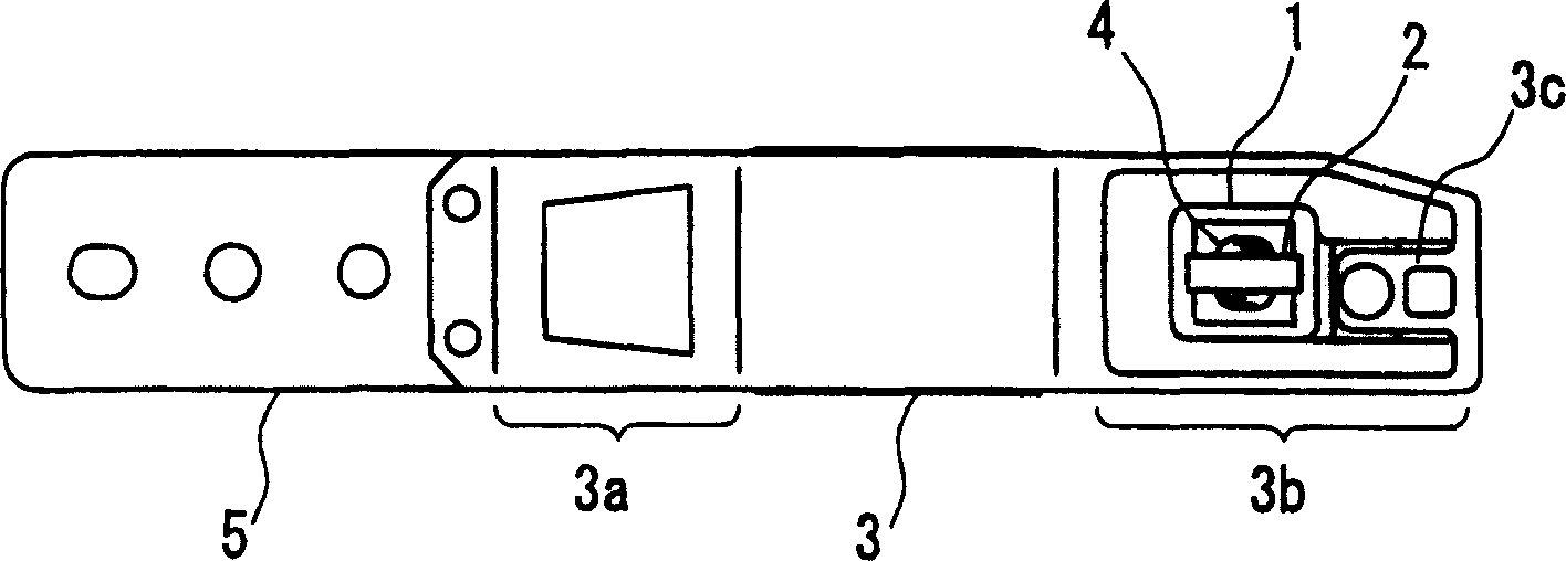
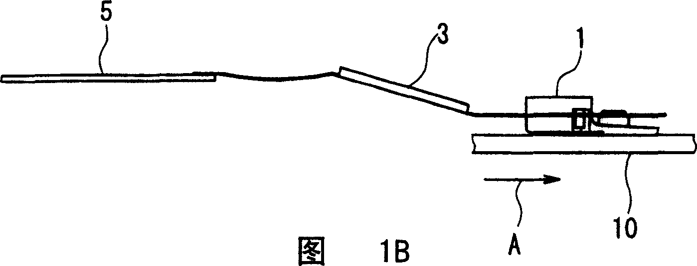
[0063] Figure 1A and FIG. 1B are a plan view and a side view showing the overall configuration of the converter supporting device in Embodiment 1 of the present invention.
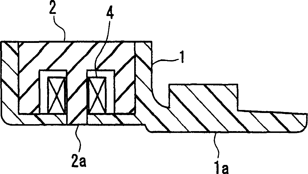
[0064] In this embodiment, the magnetic core 2 and the coil 4 have the same material and detailed structure as the magnetic core 102 and the coil 104 of the conventional example. 3 is a suspended body with one end being a fixed end and the other end being a free end with a cantilever support structure. The sliding contact 1 is installed on the free end. elastic deformation in the normal direction). The suspension body 3 corresponds to the suspension body 103 of the conventional example, and the spring portion 3a, suspension bracket 3b, and tongue portion 3c are the same as the spring portion 103a, suspension bracket 103b, and tongue portion 103c of the conventional example, respectively. 5 is a magnetic head base, which corresponds to the magnetic head base 105 of the conventional example. They are ide...
Embodiment 2
[0077] Figure 4A It is a plan view showing the installation part of the sliding contact of the inverter support device in Embodiment 2 of the present invention, Figure 4B is its side view. The magnetic core 2, the coil 4, and the disc 10 are the same as those in the first embodiment. 11 is a sliding contact, which is the same as the sliding contact 101 of the conventional example, and has a built-in magnetic core 2 and a coil 4
[0078] 13 is a suspension, which is the same as the suspension 3 in Example 1, and includes a suspension bracket 13b, but differs from the suspension 3 in Example 1 only in that it has an engaging piece interference portion 13e. The engaging piece interference portion 13e is formed by extending the suspension body 13 toward the slider 11 side.
[0079] The slider 11 of this embodiment differs from the slider 101 of the conventional example in that it has two upper engaging pieces 11d and one lower engaging piece 11e. The upper fastening piece 11...
Embodiment 3
[0089] Figure 5A It is a plan view showing the installation part of the sliding contact of the inverter supporting device in Embodiment 3 of the present invention, Figure 5B is its side view. Figure 6 is the bottom view of the sliding contact in Embodiment 3 of the present invention, Figure 7 It is a front view of the slider in Embodiment 3 of the present invention. The magnetic core 2, the coil 4, and the disc 10 are the same as those in the first embodiment. 21 is a sliding contact, which is the same as the sliding contact 11 in Embodiment 2, and is equipped with a magnetic core 2 and a coil 4. 23 is a suspension, including a suspension bracket 23b and a buckling piece interference portion 23e, which is the same as the suspension in Embodiment 2. 13 is the same.
[0090] Such as Figure 6 As shown, on the side of the sliding contact 21, as in Embodiment 1, two pairs of front openings 21b and rear openings 21c are provided, and as in Embodiment 1, the air flow is gui...
PUM
 Abstract
Description
Claims
Application Information
 - R&D Engineer
- R&D Manager
- IP Professional
- Industry Leading Data Capabilities
- Powerful AI technology
- Patent DNA Extraction
Browse by: Latest US Patents, China's latest patents, Technical Efficacy Thesaurus, Application Domain, Technology Topic, Popular Technical Reports.
© 2024 PatSnap. All rights reserved.Legal|Privacy policy|Modern Slavery Act Transparency Statement|Sitemap|About US| Contact US: help@patsnap.com