Supercharge Your Innovation With Domain-Expert AI Agents!

Refurbishment of a coated chamber component

A component and surface coating technology, applied in the field of cleaning and coating of process chamber components, can solve problems such as unacceptable, long pumping time, and unsatisfactory adhesion

Inactive Publication Date: 2006-01-04
APPLIED MATERIALS INC
View PDF6 Cites 4 Cited by
  • Summary
  • Abstract
  • Description
  • Claims
  • Application Information

AI Technical Summary

Problems solved by technology

However, it has been found that this pre-baking process results in unsatisfactory adhesion of coating layers subsequently applied to the underlying structure
Coating layers with low adhesion can flake off from underlying structures, leading to destruction of underlying structures and contamination of substrates processed in the chamber
Also, with this prebaked part, the pumping time required to achieve the proper chamber pressure is still unacceptably long

Method used


Image

  • Refurbishment of a coated chamber component
  • Refurbishment of a coated chamber component
  • Refurbishment of a coated chamber component

Examples


Embodiment Construction

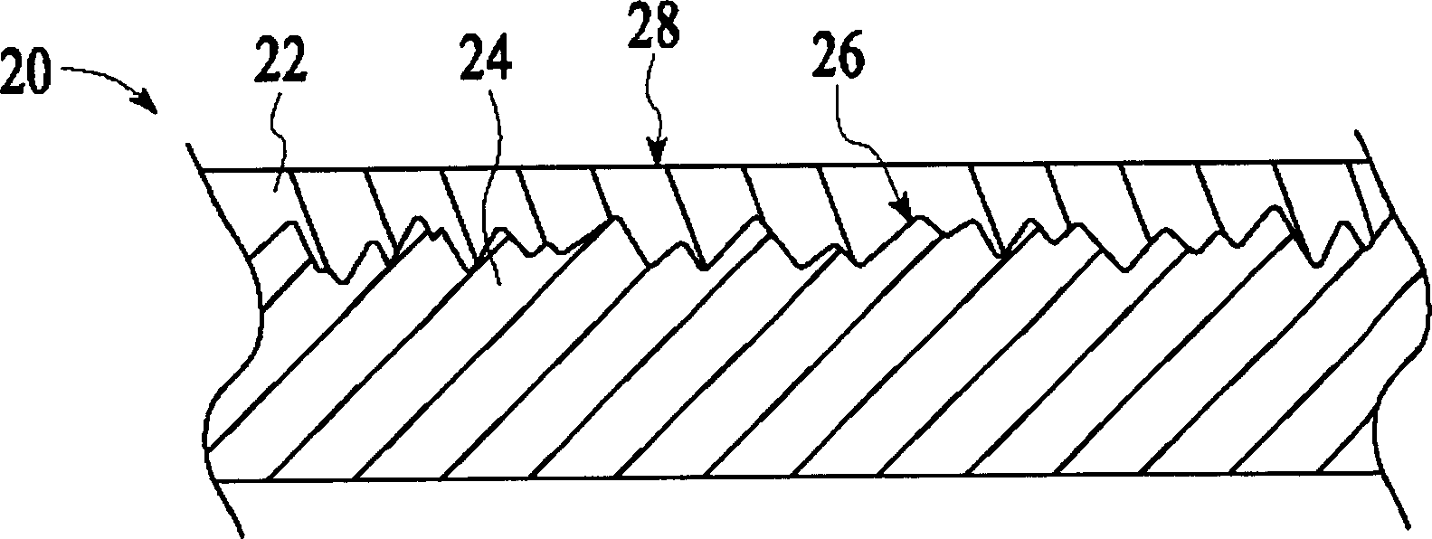
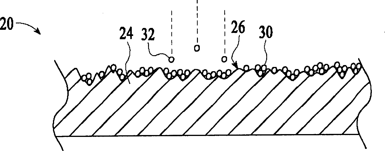
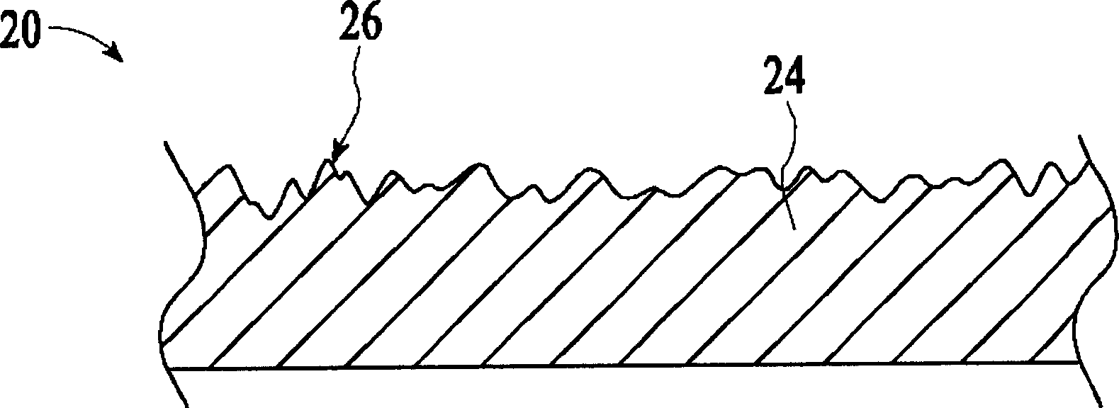
[0016] The treatment method of the present invention is suitable for cleaning and refurbishment of components 20 having a coating 22, as shown for example in FIG. 1 . This treatment method improves the cleaning and refurbishment of the component 20 and also improves the technical effect of removing volatile residues from the component 20 . Removing volatile residues can reduce the overall pumping time to achieve the desired pressure level in the chamber 106 . The processing method may be used to clean and refurbish one or more etch-susceptible components 20 in the chamber 106, including, for example, one or more portions of the gas delivery system 112 that provides the chamber Process gas in 106; substrate support 114 to support substrate 104 in chamber 106; gas energizer 116 to energize process gas; chamber housing wall 118 and shield 122 and an exhaust port 120 for exhausting gas from the chamber 106, an exemplary embodiment of all of which is shown in FIG. 3 . For example...


PUM

PropertyMeasurementUnit
surface roughnessaaaaaaaaaa

Abstract

A component of a process chamber is cleaned and refurbished. The component has a structure with an overlying coating having of a first layer. To refurbish the component, the first layer is removed to form an exposed surface on the structure. During or after the removal of the coating, the exposed surface is cleaned with a cleaning fluid, which deposits cleaning residue on the exposed surface. The exposed surface is heated in a substantially non-oxidizing atmosphere to a temperature that is sufficiently high to vaporize the cleaning residue from the surface, thereby forming a cleaned surface. A second layer is formed over the cleaned surface.

Description

Background technique [0001] The present invention relates to the cleaning and coating of process chamber components. [0002] In the processing of substrates, such as semiconductor wafers and display panels, the substrate is placed in a processing chamber and exposed to process gases to deposit or etch materials on the substrate. During this process, process residues are produced and may deposit on the inner surfaces of the chamber. For example, in a sputter deposition process, the material sputtered from the target for deposition onto the substrate is also deposited on the surfaces of other components within the chamber, such as deposition rings, shadow rings, On wall liners and focus rings. During subsequent processing cycles, deposited process residues can "scale" from the chamber surfaces onto and contaminate the substrate. [0003] To reduce contamination of the substrate by process residues, the surface of the components in the chamber can be made uneven. Process res...

Claims


Application Information

Patent Timeline
Patent Type & Authority Applications(China)
IPC IPC(8): H01L21/00C23C16/56C23C16/00H05H1/46B05D3/02B08B3/08B08B3/12B08B7/00B08B7/02C23C14/56H01J9/38H01J37/32H01L21/205H01L21/3065
CPCB08B3/08B08B7/0035C23C14/564B08B3/12H01J9/38H01J37/32431
Inventor Y·林D·徐R·哈尼C·斯托
Owner APPLIED MATERIALS INC
Features
  • R&D
  • Intellectual Property
  • Life Sciences
  • Materials
  • Tech Scout
  • Unparalleled Data Quality
  • Higher Quality Content
  • 60% Fewer Hallucinations
Learn More