Compressor

A compressor and sensor technology, applied in the field of compressors, can solve the problems of reducing the reliability of compressors, not using them, and not correcting them

Active Publication Date: 2006-01-11
코벨코컴프레서가부시키가이샤
View PDF0 Cites 6 Cited by
  • Summary
  • Abstract
  • Description
  • Claims
  • Application Information

AI Technical Summary

Problems solved by technology

Therefore, when the compressor is stopped with a small error in the detection value, the reliability related to the operation and maintenance of the compressor will still be reduced.
In addition, when the compressor is stopped and the sensor is checked, it is helpful to manage the compressor by responding to the

Method used


Image

  • Compressor
  • Compressor
  • Compressor

Examples


Embodiment Construction

[0032] Hereinafter, embodiments of the present invention will be described with reference to the drawings.

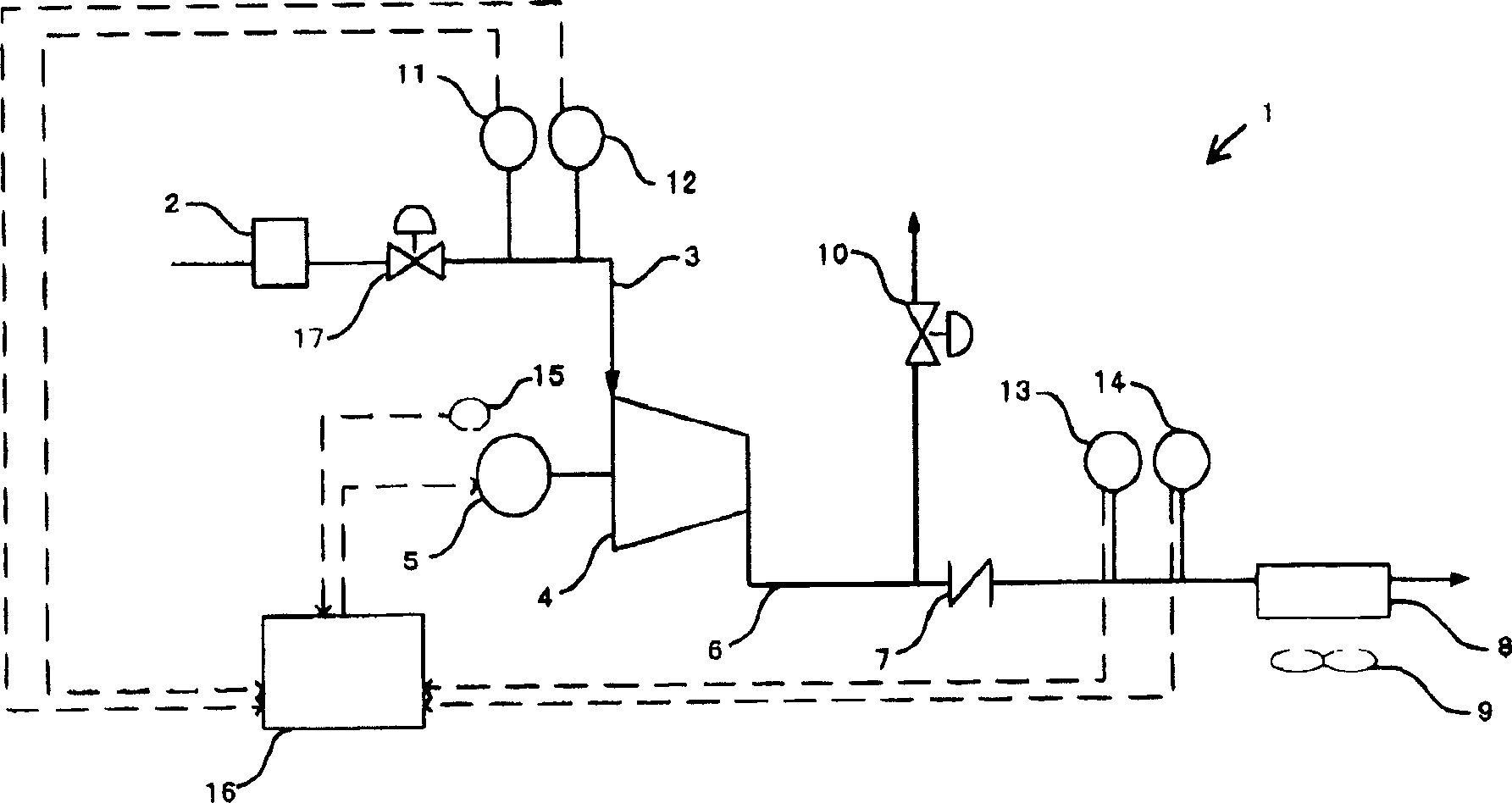
[0033] figure 1 It is a block diagram showing the configuration and information transmission of the compressor according to the embodiment of the present invention. The compressor 1 has a suction filter 2 for sucking gas into the compressor. The gas sucked by the suction filter 2 is introduced into the compressor body 4 through the suction pipe 3 . The compressor body 4 is connected to a motor 5 , and the gas is compressed in the compressor body 4 by driving the motor 5 . The compressed gas is introduced into the equipment using the compressed gas through the discharge pipe 6 . At this time, a check valve 7 is provided in the middle of the discharge pipe 6 so as not to cause backflow of the gas. In addition, a cooler 8 and a cooling fan 9 are provided on the discharge pipe 6 to adjust the temperature of the discharge gas. Furthermore, the discharge pipe 6 is provid...


PUM


Abstract

In this compressor, the detection values of the sensors are compared with a predetermined specified value to determine the degree of abnormality to discriminate the element related to the sensor, and the operation is controlled according to the degree of abnormality of the sensor and the element related to the sensor.

Description

technical field [0001] The present invention relates to a compressor. In particular, the present invention relates to a new function for ensuring reliability of compressor control and operation of the compressor. Background technique [0002] Compressors are required to supply compressed gas at a stable pressure or temperature to a supply destination. In addition, compressors are often used as application equipment in factories and the like. If the supply of compressed gas with stable pressure and temperature cannot be obtained, it will cause troubles in plant operation. Therefore, in order to realize the supply of compressed gas with stable pressure and temperature, the compressor is equipped with various sensors and control devices such as pressure sensors for monitoring pressure on the suction side and discharge side, and temperature sensors for detecting temperature. Then, the detection value of the sensor is periodically sent to the control device, and the control de...

Claims


Application Information

Patent Timeline
IPC IPC(8): F04B49/02F04D27/00
Inventor 中村元
Owner 코벨코컴프레서가부시키가이샤
Why Eureka
Try Eureka