Antenna driver

A driving device and antenna technology, which is applied in transportation and packaging, components and instruments that generate electric pulse circuits, etc., can solve the problems of false detection of the driving ECU95 and the reliability of the detection signal, and achieve the effect of reducing the number of components.

Inactive Publication Date: 2016-12-28
AISIN SEIKI KK
View PDF12 Cites 1 Cited by
  • Summary
  • Abstract
  • Description
  • Claims
  • Application Information

AI Technical Summary

Problems solved by technology

However, for example, if a detection signal is output while the antenna 91 is being driven, the drive ECU 95 may erroneously detect the signal due to an AC signal superimposed on the detection signal.
In addition, when the detection performance of the detection member 92 itself deteriorates due to the influence of the electromagnetic field when the antenna 91 is driven, the reliability of the detection signal will naturally decrease.

Method used


Image

  • Antenna driver
  • Antenna driver
  • Antenna driver

Examples


Embodiment Construction

[0055] An embodiment of the present invention is embodied as an antenna driving device of a smart entry system (registered trademark), wherein the smart entry system utilizes wireless communication with a mobile phone carried by a vehicle user to The doors are locked and unlocked.

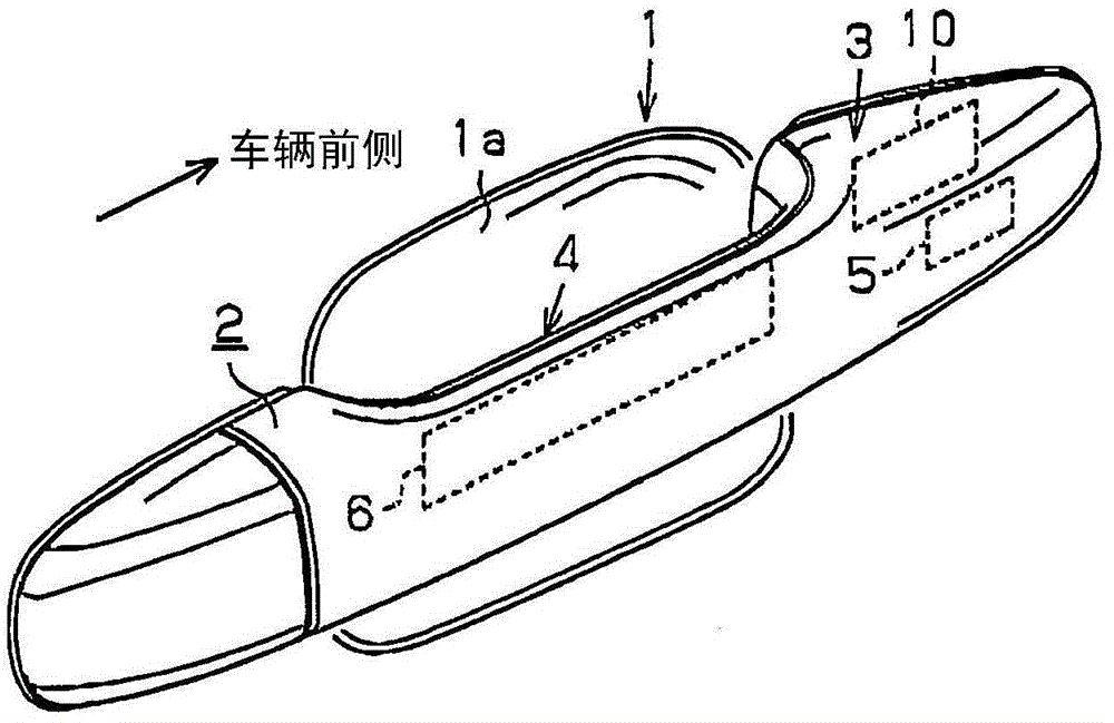
[0056] like figure 1 As shown, an outer door handle 2 is provided on a door outer panel 1 constituting a vehicle door. The outer door handle 2 extends in the front-rear direction of the vehicle, and is attached to the front and rear of the door outer panel 1 at two places. Further, a recessed portion 1 a facing the outer door handle 2 and dented inward is formed in the door outer panel 1 . This is to enable a person to easily grasp the vicinity of the center of the outside door handle 2 .

[0057] The outer door handle 2 is, for example, formed of a resin material into a hollow shape having an internal space. Then, a detection area capable of detecting the approach or contact of a person is pr...


PUM


Abstract

The present invention provides an antenna drive device capable of reducing the number of connection lines to a drive control unit without impairing the reliability of a detection member for detecting approach or contact of a person. The LF antenna (21) is driven at a resonance frequency (f1) by AC signals supplied from a drive ECU (50) via a first wire (W1) and a second wire (W2). Driven members ( 22 , 23 ) are driven at resonance frequencies ( f2 , f3 ) by AC signals supplied from a drive ECU via a first electric line and a second electric line, respectively. The sensor IC (30) is driven by direct current signals supplied from the drive ECU through the first wire and the second wire, and the sensor IC detects the approach or contact of a person, and outputs a detection signal indicating the detection to the drive ECU through the first wire . The stop control unit (30c) stops the function of the sensor IC when an AC signal supplied to the LF antenna or the driven member is detected.

Description

technical field [0001] The present invention relates to an antenna driving device for driving an antenna for transmission. Background technique [0002] Conventionally, as an antenna driving device, for example, a device described in Patent Document 1 is known. This antenna drive device is a device that switches four switching elements constituting a full-bridge circuit (H-bridge circuit) by a drive circuit of a drive control unit (drive ECU) to generate an AC signal having a predetermined frequency. The AC signal is supplied to an antenna having a resonant frequency corresponding to the frequency. In addition, in order to suppress leakage of electromagnetic waves etc. from the harness electrically connecting the drive control unit and the antenna, it has also been proposed to make the impedance values ​​of the two analog circuit units arranged between the two wires of the harness equal. [0003] prior art literature [0004] patent documents [0005] Patent Document 1: ...

Claims


Application Information

Patent Timeline
Patent Type & Authority Patents(China)
IPC IPC(8): G07C9/00B60R25/24
CPCG07C9/00309G07C2009/00793G07C2209/65H03K3/01
Inventor 田端恒博萩本将弘
Owner AISIN SEIKI KK
Why Eureka
Try Eureka