
Power electronic power device module

A technology of power devices and power electronics, which is applied in the field of power electronics power device modules, can solve the problems of module scrapping, burning, and high module manufacturing costs, and achieve the effect of weight reduction and cost reduction

Inactive Publication Date: 2006-01-25
河北华整实业有限公司
View PDF0 Cites 0 Cited by
  • Summary
  • Abstract
  • Description
  • Claims
  • Application Information

AI Technical Summary

Problems solved by technology

Due to the thickness of the bottom plate of the power electronic device module of this structure, the depth of the screw hole is generally only 5-7 threads, and the mechanical strength of the copper material is low. The working chip in the module has a large power. High temperature will be generated after electrification, and the screw is easily pulled out from the screw hole of the bottom plate under the action of the disc spring, resulting in a sharp increase in the thermal resistance between the working chip and the heat dissipation bottom plate and burning
Make the entire module scrapped, resulting in serious economic losses
In addition, the use of metal copper material as the base plate not only makes the module heavy, but also makes the manufacturing cost of the module remain high due to the rising price of non-ferrous metal materials

Method used


Image

  • Power electronic power device module

Examples


Embodiment Construction

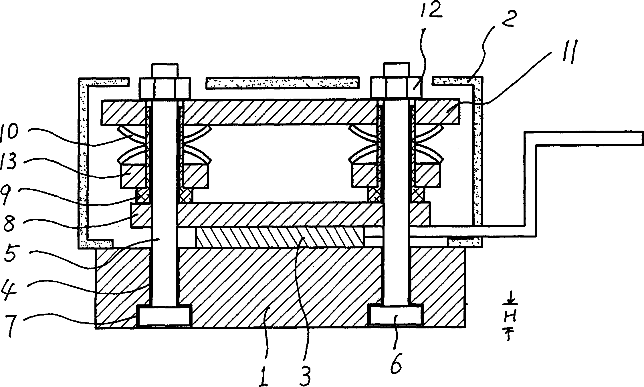
[0012] The structure and operating principle of a power electronic power device module provided by the present invention will be further described in detail below in conjunction with the accompanying drawings.

[0013] As shown in the figure, a structure of a power electronic power device module includes a base plate 1 of heat dissipation components (including water cooling or air cooling) made of metal aluminum materials, a housing 2 fixed thereto, and a fixed working chip 3 Bolt holes 4 are opened on the base plate 1, and the bottom of the bolt holes 4 (that is, the bottom of the base plate 1) is a bolt hole 7 matching the nut 6 of the bolt 5, and the bolt 5 with the nut 6 passes through the bottom of the base plate. Insert it into the bolt hole 4, and pass through the pressure block 8, the sleeve 9, the backing plate 13, the disc spring 10 and the pressure plate 11 in turn, and then tighten and fix it with the steel nut 12, so as to realize the bolt inversion (also called re...


PUM


Abstract

This invention relates to a power electronic power device module characterizing in including a base plate as the radiating fin, a working chip adhered to it, a press block through a screw rod and fixing the chip, a socket, a butterfly spring and a press plate, among which, the bottom-plate is opened with bolt holes, the bottoms of which are opened with holes matched to the caps of the bolts, the bolts with caps are plugged from the bottom of the base plate to pass through said block, socket, butterfly spring and press plate to be fixed by nuts, among which, the base plate is made of Al material. Bolt holes are opened on the base plate, the bottoms of the holes are opened with holes matched to the caps, when fixing the chip, the bolts are installed upside down.

Description

technical field [0001] The invention belongs to the technical field of semiconductor power devices for electric equipment, and in particular relates to a power electronic power device module composed of a heat dissipation base plate, a working chip, a pressure block fixed by a screw, a bushing, a disc spring and a pressure plate . Background technique [0002] At present, the structure of the power electronic device module is to use a screw to pass through the pressure plate, the disc spring, the sleeve and the pressure block in turn and screw it into the threaded screw hole opened on the bottom plate, and the working chip is fixed on the metal copper plate. Base plate heat sink made of solid material. Due to the thickness of the bottom plate of the power electronic device module of this structure, the depth of the screw hole is generally only 5-7 threads, and the mechanical strength of the copper material is low. The working chip in the module has a ...

Claims


Application Information

Patent Timeline
Patent Type & Authority Applications(China)
IPC IPC(8): H01L23/00H01L23/36
Inventor 宋希振宋晓飞
Owner 河北华整实业有限公司
Learn More