
Organic light emitting diode (OLED) with contrast enhancement features

A technology of electroluminescent devices and ambient light, which is applied in the direction of electroluminescent light sources, light sources, electric light sources, etc., and can solve problems such as inapplicable emission from devices

Inactive Publication Date: 2006-02-01
LUXELL技术有限公司
View PDF3 Cites 9 Cited by
  • Summary
  • Abstract
  • Description
  • Claims
  • Application Information

AI Technical Summary

Problems solved by technology

[0004] However, these prior art structures are not suitable for situations where it is desired to actually exploit the reflectivity of the back cathode to increase the amount of light emitted from the device
In other words, while the prior art devices described above reduce the ambient light reaching the display's back cathode, the prior art devices also tend to reduce the light emitted backwards towards the back of the display.

Method used


Image

  • Organic light emitting diode (OLED) with contrast enhancement features
  • Organic light emitting diode (OLED) with contrast enhancement features
  • Organic light emitting diode (OLED) with contrast enhancement features

Examples


Embodiment Construction

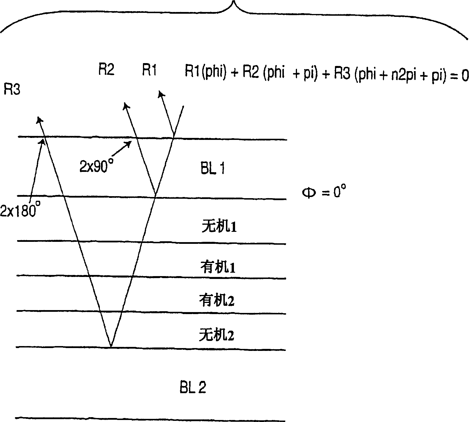
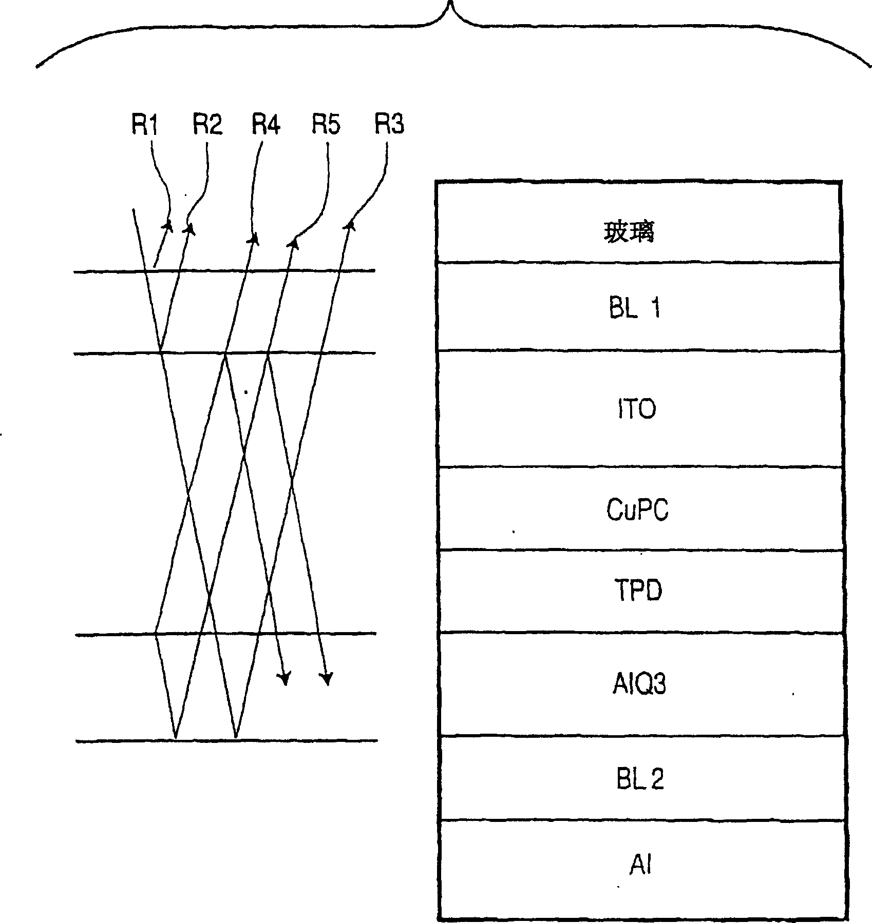
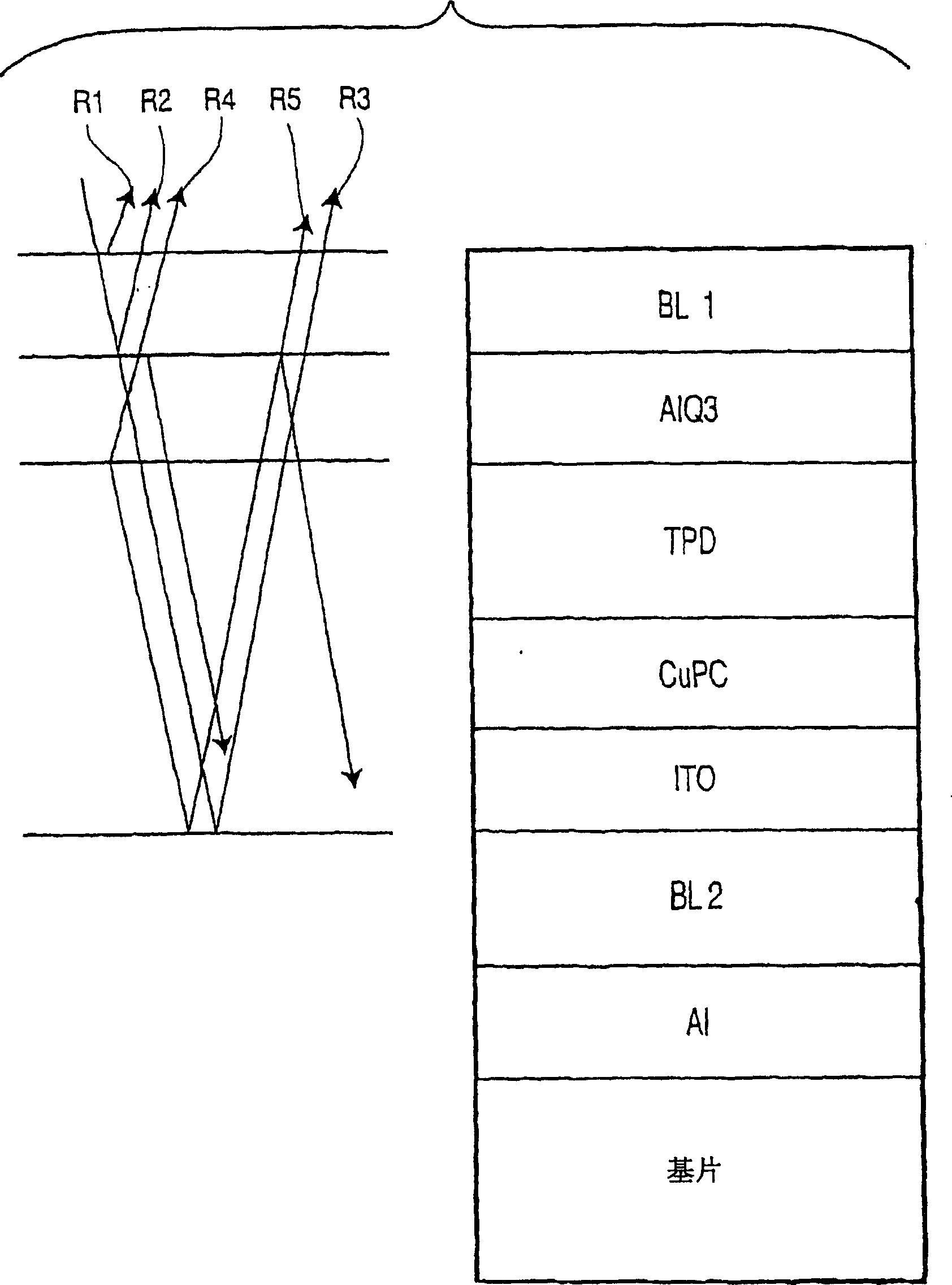
[0022] now refer to figure 1 , the semi-reflective film BL1 is arranged on one side adjacent to the microcavity, which includes: inorganic layers such as ITO, AlSiO, etc. (in figure 1 identified as "inorganic 1", "inorganic 2") between which a light-emitting layer (identified as "organic 1" and "organic 2") is arranged, and the reflective structure BL2 is arranged adjacent to the micro opposite side of the chamber. will be combined as follows figure 2 with image 3 As discussed, layer BL2 may be totally reflective or may be partially transmissive, and phase shifts light that is reflected off an additional fully reflective layer, such as an Al layer. The light-emitting layer generates light by electroluminescence and is made of a material that is generally transparent to, and induces a phase shift of, ambient light entering the device, as will be discussed in detail below.

[0023] The semi-reflective structure BL1 may comprise a single-layer film or a multi-layer film, as...


PUM


Abstract

An organic electroluminescent device is provided having emitting layers with materials and thicknesses that provide constructive optical interference of emitted light. The device includes additional layers that provide contrast enhancement through destructive optical interference of ambient light entering the device.

Description

field of invention [0001] The present invention relates to electroluminescent devices, and more particularly, to contrast enhancing filters applied to electroluminescent devices. Background of the invention [0002] Known contrast enhancing filters include optical interference filters as described in US5049780 to Dobrowoiski and US6411019 to Hofstra, the contents of which are incorporated herein by reference. In certain teachings of Dobrowolski and Hofstra, contrast enhancement is provided by optical interference components placed in front of the reflective back electrode or reflective back cathode. As described in more detail herein, reflecting ambient light off the back electrode or back cathode is used in conjunction with optical interference components to generate at least two out-of-phase ambient light waveforms that interfere with each other to cause mutual At least some cancellation of , and thereby reducing unwanted ambient light reflections from the display. [00...

Claims


Application Information

Patent Timeline
Patent Type & Authority Applications(China)
IPC IPC(8): H01L51/52
CPCH01L51/5265H01L51/5281H10K59/8791H10K59/876H05B33/24H10K50/86H10K50/852
Inventor 里查德·P·伍德大卫·J·约翰逊
Owner LUXELL技术有限公司
Learn More