Light guiding plate and manufacturing method thereof

A manufacturing method and technology for light guide plates, which are applied in optics, nonlinear optics, diffusing elements, etc., can solve the problem of low light utilization rate of light guide plates, and achieve the goal of improving light utilization rate, reducing light transmission interface, and improving light rate. Effect

Inactive Publication Date: 2006-02-08
HONG FU JIN PRECISION IND (SHENZHEN) CO LTD +1
View PDF1 Cites 3 Cited by
  • Summary
  • Abstract
  • Description
  • Claims
  • Application Information

AI Technical Summary

Problems solved by technology

[0007] In order to overcome the problem of low light utilization rate of the light guide plate in the prior art, the pres...

Method used


Image

  • Light guiding plate and manufacturing method thereof
  • Light guiding plate and manufacturing method thereof
  • Light guiding plate and manufacturing method thereof

Examples


Embodiment Construction

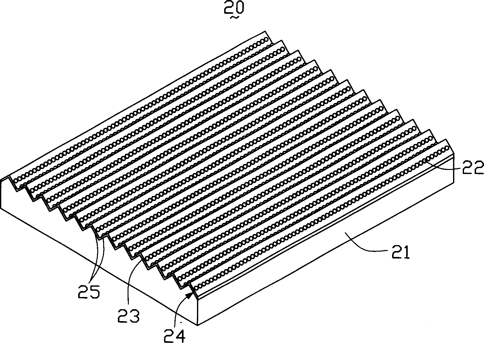
[0018] see figure 2 , is a schematic perspective view of the first embodiment of the light guide plate of the present invention. The light guide plate 20 includes a substrate 21 and a plurality of transparent particles 22 . The substrate 21 is a rectangular transparent substrate. The substrate 21 includes a surface 24 having a groove array 25 , and the groove array 25 is a V-shaped groove array. The size of the plurality of transparent particles 22 is 10 -9 Meter. The plurality of transparent particles 22 are evenly adhered on the surface through a glue layer 23 . The adhesive layer 23 is a transparent adhesive layer.

[0019] The V-shaped groove array shape of the groove array 25 can control the outgoing angle of the light and converge the outgoing light at a certain angle, which can make full use of the outgoing light and improve the light utilization rate. The groove array 25 controls the outgoing angle of the light, and matches with the viewing angle of the liquid cr...


PUM


Abstract

The invention provides a light conducting plate for liquid crystal display device, which comprises a substrate and a plurality of transparent particles, wherein the substrate includes a surface having trench arrays, the transparent particles are adhered onto the surface through a glue layer. The light conducting board has high utilization rate of light, and can effectively control the angle of departure for the light rays. The invention also provides the method of making the light conducting board.

Description

【Technical field】 [0001] The invention relates to a light guide plate used in a liquid crystal display device and a manufacturing method thereof. 【Background technique】 [0002] In recent years, with the colorization and enlargement of liquid crystal displays, their application fields are more extensive, such as mobile phones, notebook computers, and various desktop computers. Since the liquid crystal display is a passive component and cannot emit light by itself, a light source system needs to be used as the light source of the liquid crystal display. Such as the backlight module, in which the light guide plate is an important component in the backlight module, which is used to guide the transmission direction of the light beam emitted from the light source, and convert the line light source or point light source into a surface light source to emit. [0003] At present, the manufacturing methods of the light guide plate can be divided into etching method (Etching), laser p...

Claims


Application Information

Patent Timeline
IPC IPC(8): G02F1/1335G02B5/02
Inventor 李俊佑蔡明江江宗韦黄全德
Owner HONG FU JIN PRECISION IND (SHENZHEN) CO LTD
Why Eureka
Try Eureka