Electroluminescent device and method of manufacturing thereof

A technology of electroluminescent element and manufacturing method, which is applied in the field of light-emitting device and the manufacture of the aforementioned electroluminescent element, and can solve the problems of lack of solubility and the like

Inactive Publication Date: 2006-02-08
SEMICON ENERGY LAB CO LTD
View PDF2 Cites 1 Cited by
  • Summary
  • Abstract
  • Description
  • Claims
  • Application Information

AI Technical Summary

Problems solved by technology

However, these metal complexes are generally mostly substances that lack solubility

Method used


Image

  • Electroluminescent device and method of manufacturing thereof
  • Electroluminescent device and method of manufacturing thereof
  • Electroluminescent device and method of manufacturing thereof

Examples


Embodiment approach 1

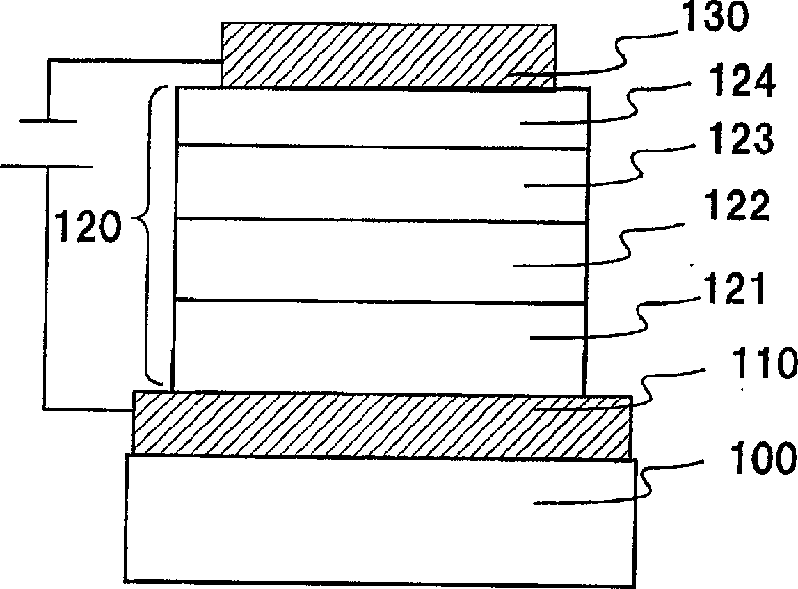
[0109] In Embodiment 1, the above-mentioned organic compound (ligand) and metal salt are co-evaporated and heated, and the structure of the electroluminescent element when the layer thus obtained is formed as a light-emitting layer is defined by figure 1 Be explained.

[0110] figure 1 The structure is as follows: a first electrode 110 is formed on a substrate 100, an electroluminescent layer 120 is formed on the first electrode 110, and a second electrode 130 is formed thereon.

[0111] It should be noted that, here, as the material used for the substrate 100 , as long as it is used for a conventional electroluminescent element, for example, a material made of glass, quartz, transparent plastic, etc. can be used.

[0112] In addition, in Embodiment 1, the first electrode 110 functions as an anode, and the second electrode 130 functions as a cathode.

[0113] That is, the first electrode 110 is formed of an anode material. Here, as an anode material that can be used, metals,...

Embodiment approach 2

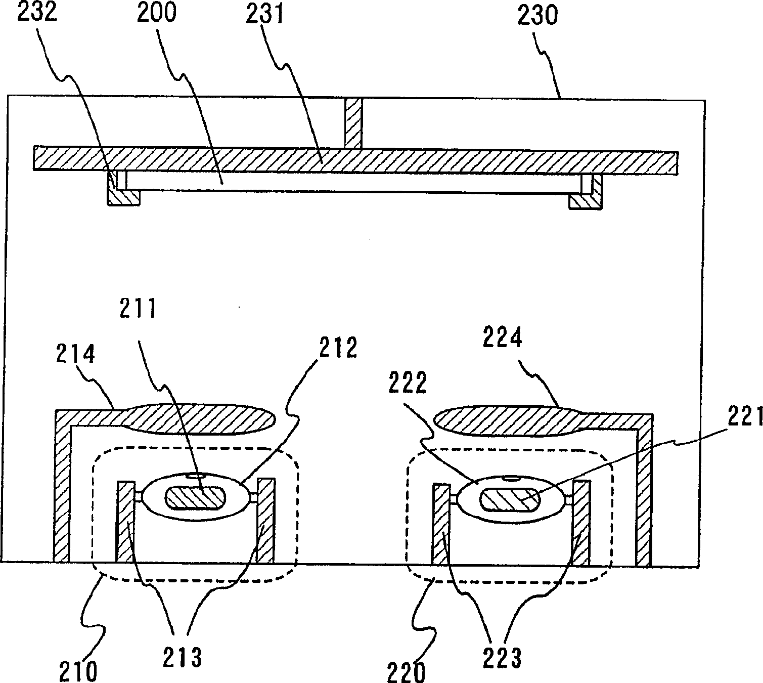
[0131] In Embodiment 2, for the above co-evaporation method, use figure 2 Describe its specific shape. It should be noted, figure 2 A cross-sectional view of the vapor deposition machine. As the shape of the vapor deposition source, there are types using batteries, types using conductive heating elements, etc. figure 2 Shown in is the case where a conductive heating element is used.

[0132] First, the container a212 filled with the aforementioned organic compound 211 is fixed on the electrode a213 located at the bottom of the vapor deposition chamber 230 . Similarly, on the electrode b223, the container b222 filled with the aforementioned metal salt 221 is fixed. In addition, the substrate 200 on which the first electrode of the electroluminescent element and the like are deposited is fixed by the substrate holder 232 on the rotating disk 231 positioned above the vapor deposition chamber 230 so that the first electrode faces downward.

[0133] Then, by applying a volt...

Embodiment 1

[0137] In this example, a method for synthesizing an organic compound used for co-evaporation will be specifically exemplified.

[0138] Mix 20 ml of a methanol solution of 1.72 g of 1-hydroxy-2-naphthaldehyde and 50 ml of a methanol solution of 0.57 g of 1,2-cyclohexanediamine (the molar ratio at this time is 2:1), and stir for 1 to 2 hours. As a result, yellow crystals were precipitated. Utilize vacuum filtration to take out this precipitate, it is dried with vacuum oven, obtains 1,2-bis(2-hydroxyl-1-naphthylene)-cyclohexanediamine (hereinafter referred to as na2-cHex) (such as Shown in structural formula (17), the crystallization temperature is 120°C, the melting point is 205°C, and the decomposition temperature is 305°C.

[0139]


PUM

PropertyMeasurementUnit
crystallization temperatureaaaaaaaaaa
melting pointaaaaaaaaaa
decomposition temperatureaaaaaaaaaa

Abstract

Production of an electroluminescent element characterized in that even with respect to a material whose vapor deposition or wet coating is difficult in the form of a metal complex, a metal salt and an organic compound (ligand) being raw materials for a metal complex are coevaporated and deposited on a substrate so as to form a complex on the substrate, thereby forming a film comprising the metal complex, and that an electroluminescent element is fabricated with the use of the film resulting from the co-evaporation deposition. It is requisite that the organic compound (ligand) have a functional group capable of easily releasing proton to thereby exhibit anionic property (and couple with a metal) and a functional group having a lone electron pair for coordinate bond with a metal.

Description

technical field [0001] The present invention relates to an electroluminescent element in which an electroluminescent layer is sandwiched between a pair of electrodes, and a light-emitting device using the electroluminescent element. It also relates to a method of manufacturing the aforementioned electroluminescence element. Background technique [0002] Electroluminescence devices using organic compounds as light emitters are thin and lightweight, high-speed response, DC low-voltage drive, and wide-angle, and are attracting attention as next-generation flat panel display devices. [0003] The light-emitting mechanism of the electroluminescent element is to apply an external voltage to the electroluminescent layer sandwiched between a pair of electrodes, inject electrons and holes as carriers from the cathode and anode respectively, and regenerate them at the luminescent center in the electroluminescent layer. After combining to form molecular excitons, energy is released in...

Claims


Application Information

Patent Timeline
Patent Type & Authority Applications(China)
IPC IPC(8): C09K11/06H05B33/14H05B33/10H01L51/00H01L51/50
CPCH01L51/5012H01L51/0078H01L51/0059C09K11/06C09K2211/188H05B33/14H01L51/0077H10K85/631H10K85/311H10K85/30H10K50/11
Inventor 中岛晴惠濑尾哲史
Owner SEMICON ENERGY LAB CO LTD
Why Eureka
Try Eureka