Air filter for engine

An air filter and engine technology, applied in the direction of combustion air/combustion-air treatment, charging system, machine/engine, etc., can solve the problems of engine flameout, incomplete combustion, etc.

Inactive Publication Date: 2006-02-15
KYMCO
View PDF0 Cites 11 Cited by
  • Summary
  • Abstract
  • Description
  • Claims
  • Application Information

AI Technical Summary

Problems solved by technology

[0005] The main purpose of the present invention is to provide an air filter device for an engine, which can make the air containing water vapor entering the air filter naturally achieve the separation of water and gas by the gravity of the water gas itself, so that the water can be separated from the box body. To solve the problem of engine flameout or incomplete combustion caused by excessive water vapor

Method used


Image

  • Air filter for engine
  • Air filter for engine
  • Air filter for engine

Examples


Embodiment Construction

[0028] In order to understand the structure of the present invention and the effects that can be achieved more easily, the illustrations are as follows:

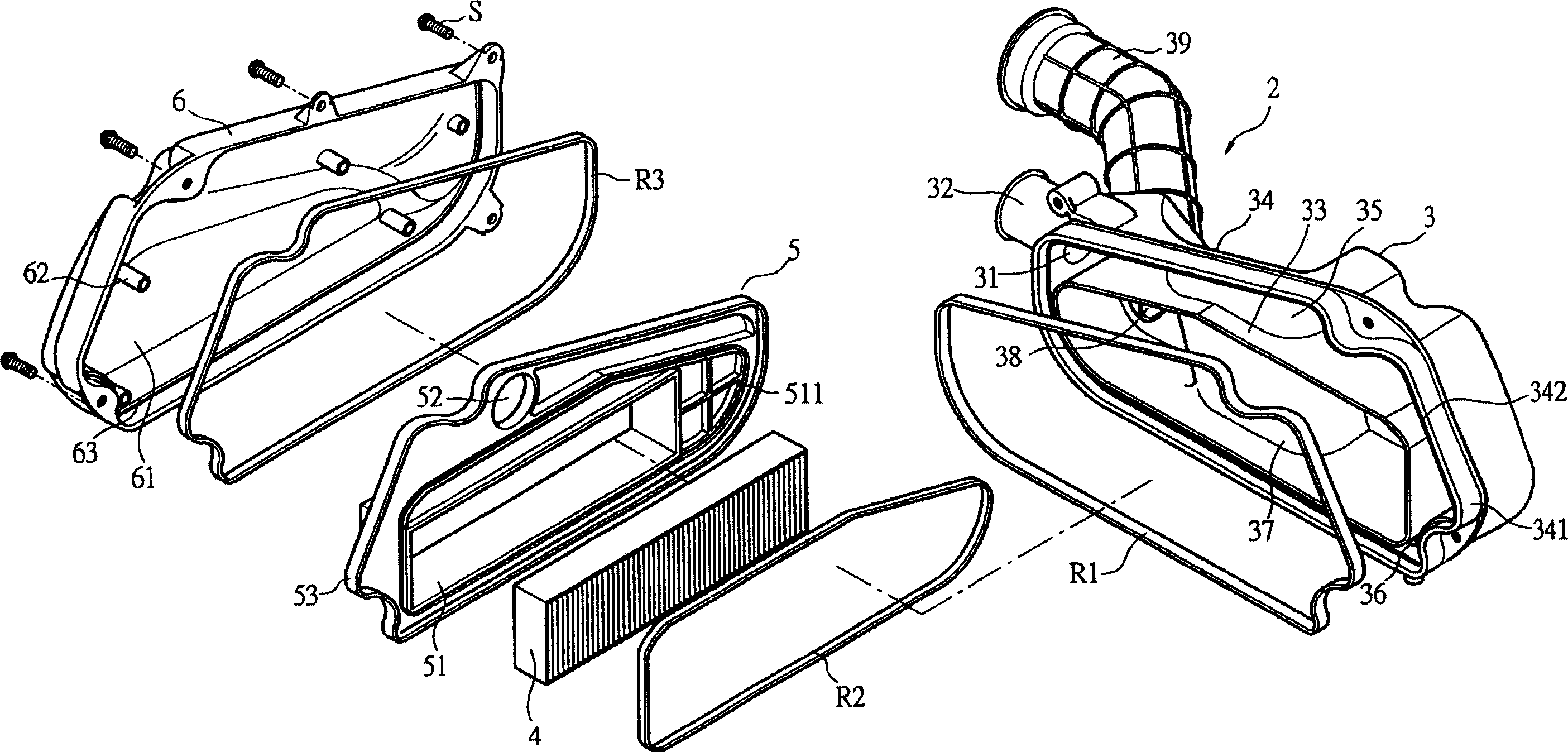
[0029] First, see figure 2 , The air filter 2 of the present invention is mainly composed of a box body 3, a filter element 4, and a cover body 6.

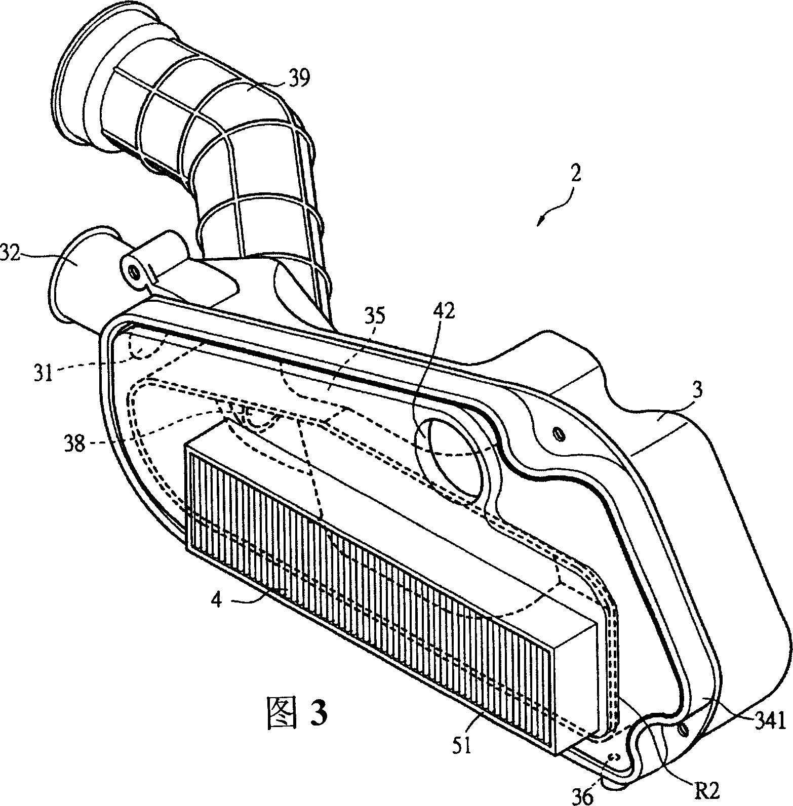
[0030] The box body 3 is a box-shaped body, an air inlet 31 is provided at its front end, an air inlet pipe 32 is connected to the front end of the air inlet 31, and a partition plate surrounding the box body 3 is provided inside the box body 3 33, the partition plate 33 and the ring wall 34 of the box body 3 can just form an air channel 35, and the air channel 35 is an annular channel extending from the air inlet 31 along the box body 3. In addition, on the air passage 35 and at the bottom of the ring wall 34 of the box body 3, a drain hole 36 is provided. An outlet chamber 37 is defined at the center of the box body 3 by a partition 33 , an air outlet 38 is provided on the o...


PUM


Abstract

This invention relates to an air filtrating device with engine, this device includes a case, a filtrating component, and a case cover, wherein a clapboard is arranged in the case, and it through the clapboard and the looping wall of the case and the fixing board to form an air channel, and a tapping hole is arranged at the bottom of the case and on the air channel, the filtrating component is fixed on the fixing board, which joints to the case, and a ventilating outlet and outlet slot are arranged on the fixing board, which are applied for the fixing of the filtrating component, and the cover is correspondent with the shape of the case and can be fixed on the case with snail, and the fixing board stably joints to case by being propped by the top pole of the case when the case fixes with the cover by snail; and this invention uses the air channel in the case to separate the excessive water in the outer air and vent it by the venting hole to solve the engine flameout or uncompleted burning problems for excessive high hydrosphere.

Description

【Technical field】 [0001] The invention relates to an engine air filter device. 【Background technique】 [0002] Conventional air filter 1, please refer to shown in Fig. 1, it is mainly made of a box body 11, a cover body 12 and a filter element 13, wherein, there is an accommodating chamber in the box body 11, as Clean room 111 is used, and this box body 11 is provided with an air inlet 112 that communicates with clean room 111, and this air inlet 112 is externally connected with an air inlet pipe 113, and is provided with an air outlet 114 on one side of box body 11 in addition, and this outlet An air outlet pipe 115 can be connected to the air port 114, and the air outlet pipe 115 can be connected with a carburetor or a throttle body (not shown here). The filter element 13 is disposed between the air inlet 112 and the air outlet 114 . The cover body 12 can be locked on the side of the box body 11 through screw fastening elements. [0003] The conventional air filter 1 is...

Claims


Application Information

Patent Timeline
Patent Type & Authority Applications(China)
IPC IPC(8): F02M35/024F02M35/16
Inventor 陈宪辉
Owner KYMCO
Why Eureka
Try Eureka