Fuse box

A technology of fuses and fuse boxes, applied in the direction of electrical components, circuits, emergency protection devices, etc., can solve the problems of tongue terminal part 55 damage, poor insertion operation efficiency, breakage, etc., to prevent deformation or breakage, support Well-balanced, overall height-reducing effect

Inactive Publication Date: 2006-02-22
YAZAKI CORP
View PDF0 Cites 1 Cited by
  • Summary
  • Abstract
  • Description
  • Claims
  • Application Information

AI Technical Summary

Problems solved by technology

[0012] In addition, in order to install the fuse 50 into the fuse mounting portion 60, each tongue terminal portion 55 must be clamped by the gripping portions 61a and 61a of the mating terminal 61 provided on the In the deep bottom where the guide wall 62 and the insulating wall 63 are closed, the efficiency of the insertion operation is not good
[0013] Also, the tongue terminal portion 55 of the flat terminal 51 on the fuse element 56 protrudes considerably outwardly from the insulating case 53, so that there is a problem encountered in that, due to contact between a plurality of fuses 50 during transportation or the like, contact with each other, the tongue terminal portion 55 on these fuses can be damaged, and the fusible portion 52 is prone to deformation and fracture under the external force applied to the tongue terminal portion 55 when it comes into contact with other components

Method used


Image

  • Fuse box
  • Fuse box
  • Fuse box

Examples


Embodiment Construction

[0039] Preferred embodiments of the fuse of the present invention will be described in detail below with reference to the accompanying drawings.

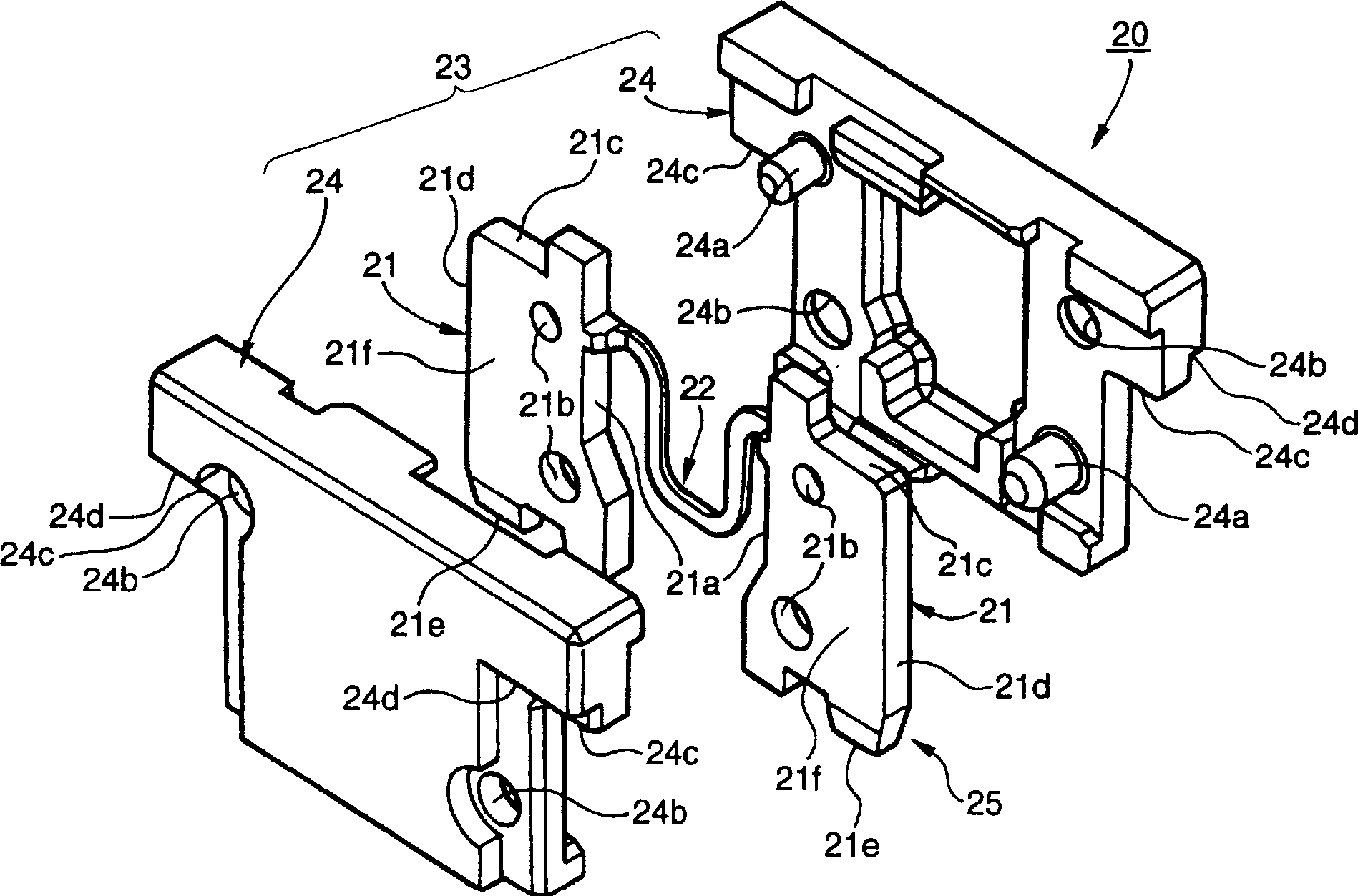
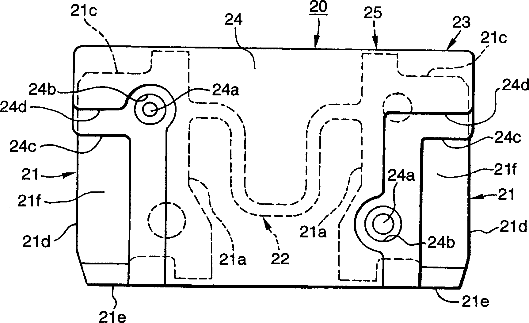
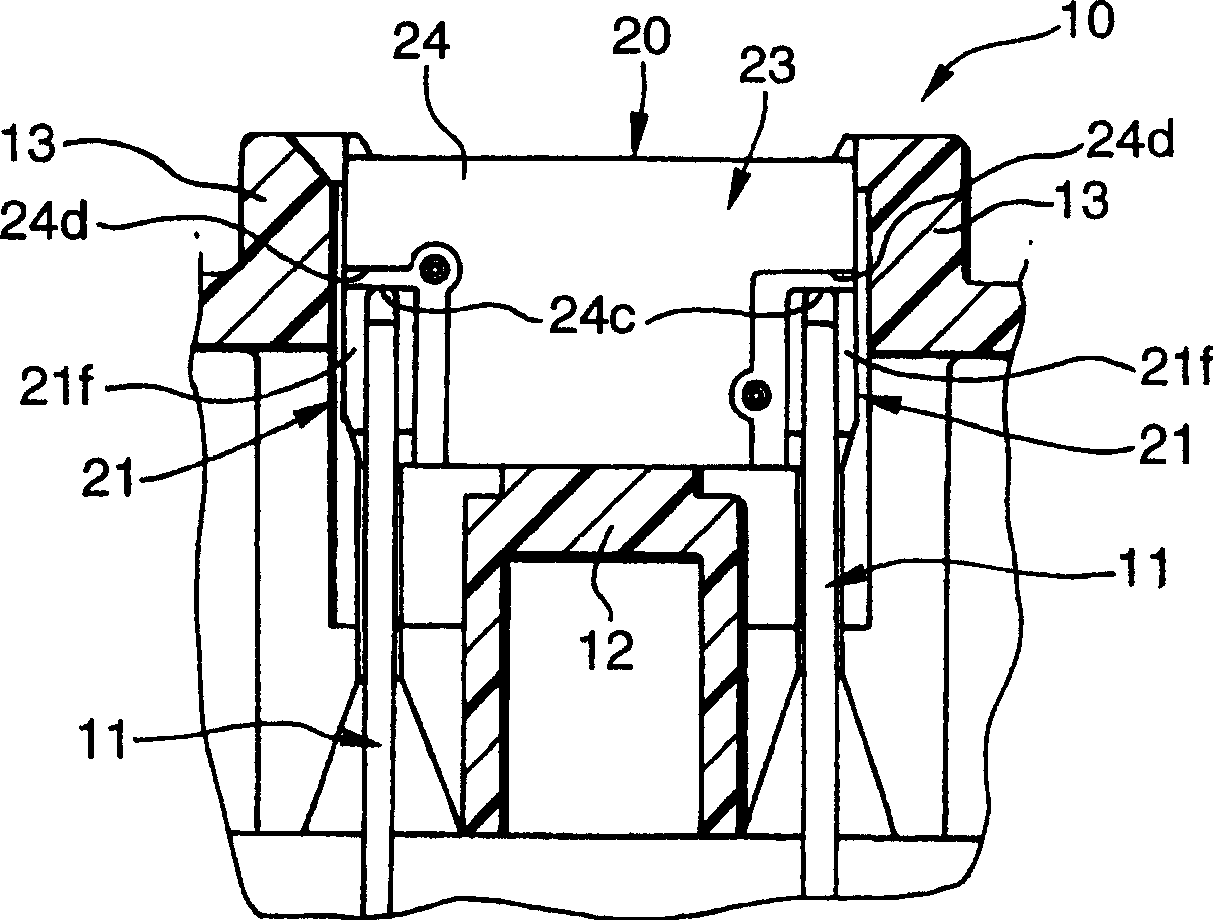
[0040] figure 1 is an exploded perspective view showing a first embodiment of the fuse of the present invention, figure 2 Yes figure 1 front view of the fuse in the image 3 and 4 are shown respectively figure 1 Front and side views of the state in which the fuse in is installed in the fuse mounting section.

[0041] The fuse 20 in the first embodiment is a chip fuse in which a fuse element 25 is provided in an insulating case 23, and the fuse element 25 has a fusible part 22 arranged in a pair of parallel Between the flat terminal parts 21 and 21.

[0042] Each flat terminal portion 21 has a substantially rectangular shape, and a fusible portion 22 having a predetermined cross-sectional area extends between opposing inner side edges 21 a and 21 a of the flat terminal portions 21 and 21 .

[0043] The insulating case 23 i...


PUM


Abstract

A fuse (20) includes a fuse element (25), having a fusible portion (22) provided between inner side edges (21a) of a pair of parallel flat-plate terminal portions (21, 21), and an insulating housing (23) covering the inner side edges (21a) of the flat-plate terminal portions (21) and the fusible portion (22). A middle portion (21f) of each of the flat-plate terminal portions (21), located at the lateral position relative to the fusible portion (22), is fixedly gripped by a mating terminal (11) of a fuse mounting portion, so that the flat-plate terminal portion is electrically connected to the mating terminal.

Description

[0001] This application is a divisional application of the invention patent application named "fuse" and application number 00819534.X filed by Yazaki General Industry Co., Ltd. technical field [0002] The present invention relates to a fuse, and more particularly, the present invention relates to an ablade-type fuse in which a fuse element is mounted inside an insulating housing, the fuse element having a fusible portion, The fusible portion is disposed between a pair of parallel flat terminal portions. Background technique [0003] Figure 7 The illustrated prior art fuse 50 is a blade fuse in which a fusible portion 56 is provided between a pair of parallel metal flat terminals 51 and 51 (hereinafter referred to as "flat terminals"). The fuse element 56 is formed, and the proximal end portion (the end portion where the fusible portion 52 is provided) of the fuse element 56 is accommodated in an insulating case 53 . [0004] Each flat terminal 51 includes a terminal body...

Claims


Application Information

Patent Timeline
Patent Type & Authority Applications(China)
IPC IPC(8): H01H85/045H01H85/22H01H85/56H01H85/041H01H85/08H01H85/147H01H85/153H01H85/157H01H85/165H01H85/175H01H85/20
CPCH01H85/2035H01H85/0417H01H85/045
Inventor 远藤隆吉大桥纪弘下地映次
Owner YAZAKI CORP
Why Eureka
Try Eureka