Lifting platform for building decoration

A lifting platform and architectural decoration technology, which is applied in the direction of hoisting devices, lifting equipment safety devices, etc., can solve the problems of small operating range, low safety factor, time-consuming and laborious, etc., to expand the working range, facilitate adjustment, and improve safety. The effect of the coefficient

Inactive Publication Date: 2018-10-09
郑州市建筑设计院
View PDF1 Cites 4 Cited by
  • Summary
  • Abstract
  • Description
  • Claims
  • Application Information

AI Technical Summary

Problems solved by technology

[0002] In the prior art: the patent of authorized publication number CN 207259104 U discloses a building lifting platform for outdoor construction and interior decoration, including a lifting base, the top center of the lifting base is provided with a retractable groove, and the retractable The top of the slot is connected with a backing plate through a telescopic folding bracket. The building lifting platform used for outdoor construction and interior decoration is mainly composed of a lifting base and an operating table. Bracket, when building outdoors, the telescopic folding bracket can be extended through the XTL100 electric telescopic rod, so that the operating table and the lifting base are separated, and the operating table is raised to facilitate the outdoor work of construction workers. The operating table can also be separated, and the It is hung on the crane and used for outdoor operation of high-rise buildings. During interior decoration, the bayonet pin can be snapped into the ferrule, and the bottom support structure can be connected with the operation table, and it can be moved indoors by wheels. The working range is small, and the lifting platform needs to be moved frequently, which is time-consuming and laborious. At the same time, the lifting platform is supported by a single wheel, and the wheels are easy to move, with poor balance and low safety factor

Method used


Image

  • Lifting platform for building decoration
  • Lifting platform for building decoration

Examples


Embodiment Construction

[0013] The following will clearly and completely describe the technical solutions in the embodiments of the present invention with reference to the accompanying drawings in the embodiments of the present invention. Obviously, the described embodiments are only some, not all, embodiments of the present invention. Based on the embodiments of the present invention, all other embodiments obtained by persons of ordinary skill in the art without making creative efforts belong to the protection scope of the present invention.

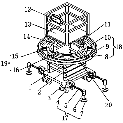
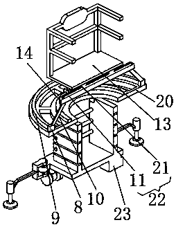
[0014] see Figure 1-2 , the present invention provides a technical solution: a lifting platform for architectural decoration, including a base 1, the bottom of the base 1 is respectively equipped with universal wheels 3 and a power supply 23, the side of the base 1 is equipped with a first support device 17, the base 1 A hydraulic lift 2 is installed on the top of the hydraulic lift 2, and a shock absorber 20 is installed on the top of the hydraulic lift 2, a...


PUM


Abstract

The invention discloses a lifting platform for building decoration. The lifting platform for the building decoration comprises a base, wherein universal wheels and a power supply are correspondingly mounted at the bottom part of the base; a first supporting device is mounted on the side surface of the base; a hydraulic lifting machine is mounted on the top part of the base, and a damping seat is mounted on the top part of the hydraulic lifting machine; an angle adjusting device is mounted on the top part of the damping seat, and a mounting rack is fixed to the top part of the angle adjusting device; and a horizontal adjusting device is mounted on the mounting rack. According to the lifting platform for the building decoration, the lifting platform is supported through the first supportingdevice, and the first supporting device is high in supporting balancing performance, so that the safety coefficient of the lifting platform is greatly improved; the working angle of the horizontal adjusting device is adjusted through the angle adjusting device, and the horizontal working position of the operating platform is adjusted through the horizontal adjusting device, and the flexibility ishigh, and the convenience of adjusting is ensured; the working range of the supporting platform is expanded; the trouble of frequently moving the lifting platform is avoided; and both time and force can be saved.

Description

technical field [0001] The invention relates to the technical field of lifting platforms, in particular to a lifting platform for architectural decoration. Background technique [0002] In the prior art: the patent of authorized publication number CN 207259104 U discloses a building lifting platform for outdoor construction and interior decoration, including a lifting base, the top center of the lifting base is provided with a retractable groove, and the retractable The top of the slot is connected with a backing plate through a telescopic folding bracket. The building lifting platform used for outdoor construction and interior decoration is mainly composed of a lifting base and an operating table. Bracket, when building outdoors, the telescopic folding bracket can be extended through the XTL100 electric telescopic rod, so that the operating table and the lifting base are separated, and the operating table is raised to facilitate the outdoor work of construction workers. The...

Claims


Application Information

Patent Timeline
Patent Type & Authority Applications(China)
IPC IPC(8): B66F11/04B66F13/00B66F17/00
CPCB66F11/04B66F13/00B66F17/006
Inventor 崔胜田净沙
Owner 郑州市建筑设计院
Why Eureka
Try Eureka