Overvoltage protection device with initiation electrode under vacuum environment

A vacuum environment and protection device technology, applied in emergency protection circuit devices, overvoltage action switches, circuits, etc., can solve the problems of low research level of overvoltage protection devices, achieve the effect of reducing response delay and reducing influencing factors

Inactive Publication Date: 2006-02-22
XI AN JIAOTONG UNIV
View PDF0 Cites 13 Cited by
  • Summary
  • Abstract
  • Description
  • Claims
  • Application Information

AI Technical Summary

Problems solved by technology

The domestic research work on overvoltage protection devices for first-level lightning protection has just started, and the research level of overvoltage protection devices with large current capacity, higher protection level and better consistency is relatively low

Method used


Image

  • Overvoltage protection device with initiation electrode under vacuum environment
  • Overvoltage protection device with initiation electrode under vacuum environment

Examples


Embodiment 1

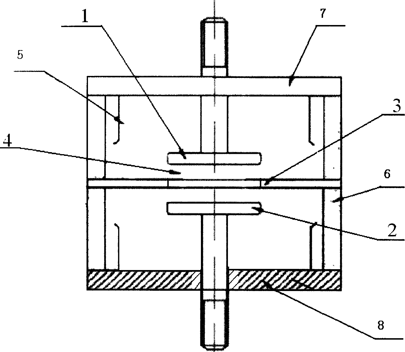
[0010] Example 1, see figure 1 , the present invention includes the main discharge electrodes 1 and 2 arranged relatively parallel in the insulating airtight casing 6 and the disc-shaped trigger electrode 3 between the main discharge electrodes 1 and 2, the main discharge electrode 1 and the main discharge electrode 2 The distance of the discharge gap 4 is 0.5 mm to 2 mm, and a shielding cover 5 is arranged around the main discharge electrodes 1 and 2, and the main discharge electrodes 1 and 2 are welded together through the sealing end cap 7 and the sealing end cap 8 and the insulating shell 6 respectively, And the pressure inside the insulating airtight casing 6 is 10-3-10-4Pa.

Embodiment 2

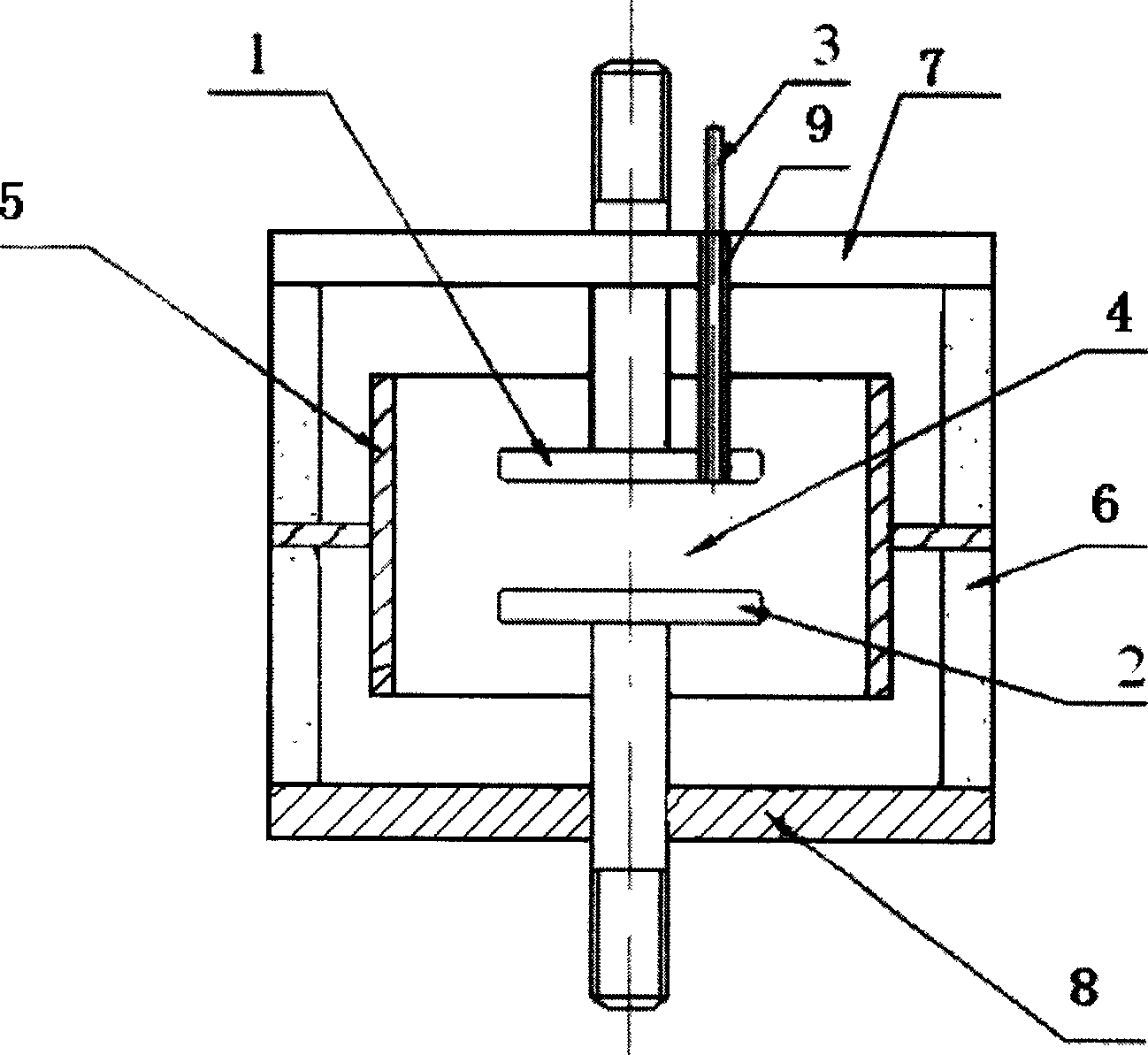
[0011] Example 2, see figure 2 , the present invention includes the main discharge electrodes 1 and 2 arranged relatively parallel in the insulating airtight casing 6 and the trigger electrode 3 embedded in the main discharge electrode 1 or the main discharge electrode 2, the trigger electrode 3 is connected to the main discharge electrode through the insulating member 9 1 or the main discharge electrode 2 is isolated, and the distance between the main discharge electrode 1 and the discharge gap 4 of the main discharge electrode 2 is 0.5 mm to 2 mm. A shielding cover 5 is also arranged around the main discharge electrode 1 and the main discharge electrode 2, and the main discharge electrodes 1 and 2 are welded together by the sealing end cap 7 and the sealing end cap 8 and the insulating airtight casing 6 respectively, and the insulating airtight casing 6 The pressure is 10 -3 ~10 -4 Pa.

[0012] In order to ensure the vacuum degree in the insulating and airtight casing 6,...


PUM


Abstract

Disclosed an over-voltage protective unit with a initiating electrode in a vacuum condition, comprises main discharging electrodes which are parallel mounted in a insulation sealed housing; initiating electrodes mounted between main discharging electrodes or pole initiating electrodes embedded in main discharging electrodes and separated from the main discharging electrodes by insulation components, while the main discharging electrodes and the initiating electrodes are individually closed by end caps in the insulation sealed housing and the pressure outside the housing ranges from 10-3~10-4 pa. When the voltage is over, initiating electrode and one parallel electrode will initiate the disruptive discharge followed by disruptive discharge occurs between two parallel electrodes. Said structure can decrease the effect between the condition of electrode surface and the disruptive discharge between two electrodes, reduce the response delay to over-voltage, attain better consistency of discharging voltage and higher over-voltage protective lever.

Description

technical field [0001] The invention relates to an overvoltage protection device, in particular to an overvoltage protection device with an initiating electrode in a vacuum environment for overvoltage protection. Background technique [0002] With the rapid development of the information industry, people have paid great attention to the harm caused by atmospheric overvoltage and operating overvoltage in the system. A large number of reports have been made on spark switches with various electrode shapes as overvoltage protection elements and devices. Among them, the gap-type overvoltage protection device of German Phoenix Contact Co., Ltd. and the surge protector with the core of high-energy discharge tube of France CITEL are representative. The technology of German Phoenix Contact Co., Ltd. is similar to the early structure of the high-voltage arrester. Two angular electrodes placed in a "V" shape are used to form a spark gap. When the gap is ignited, an arc is generated be...

Claims


Application Information

Patent Timeline
Patent Type & Authority Applications(China)
IPC IPC(8): H02H7/22H01H83/10H01T1/00
Inventor 姚学玲陈景亮
Owner XI AN JIAOTONG UNIV
Why Eureka
Try Eureka