

A flexible, tubular device e.g. a bellows
A bellows and tubular technology, applied in the field of use of devices, can solve problems such as large data changes, and achieve the effects of reducing stress level, improving the structure of flexible devices, and increasing the length of life.
Inactive Publication Date: 2006-02-22
NORSK HYDRO ASA
View PDF0 Cites 7 Cited by
- Summary
- Abstract
- Description
- Claims
- Application Information
AI Technical Summary
Problems solved by technology
Furthermore, the literature is limited in terms of estimating the fatigue data used to calculate the various current standard spacings, which vary greatly when the pitch-to-height ratio of the surround changes, for example
Method used
View moreImage
Smart ImageViewing Examples

Examples
example 1
[0039]
example 2
[0041]
example 3
[0043]
Login to View More PUM
 Abstract
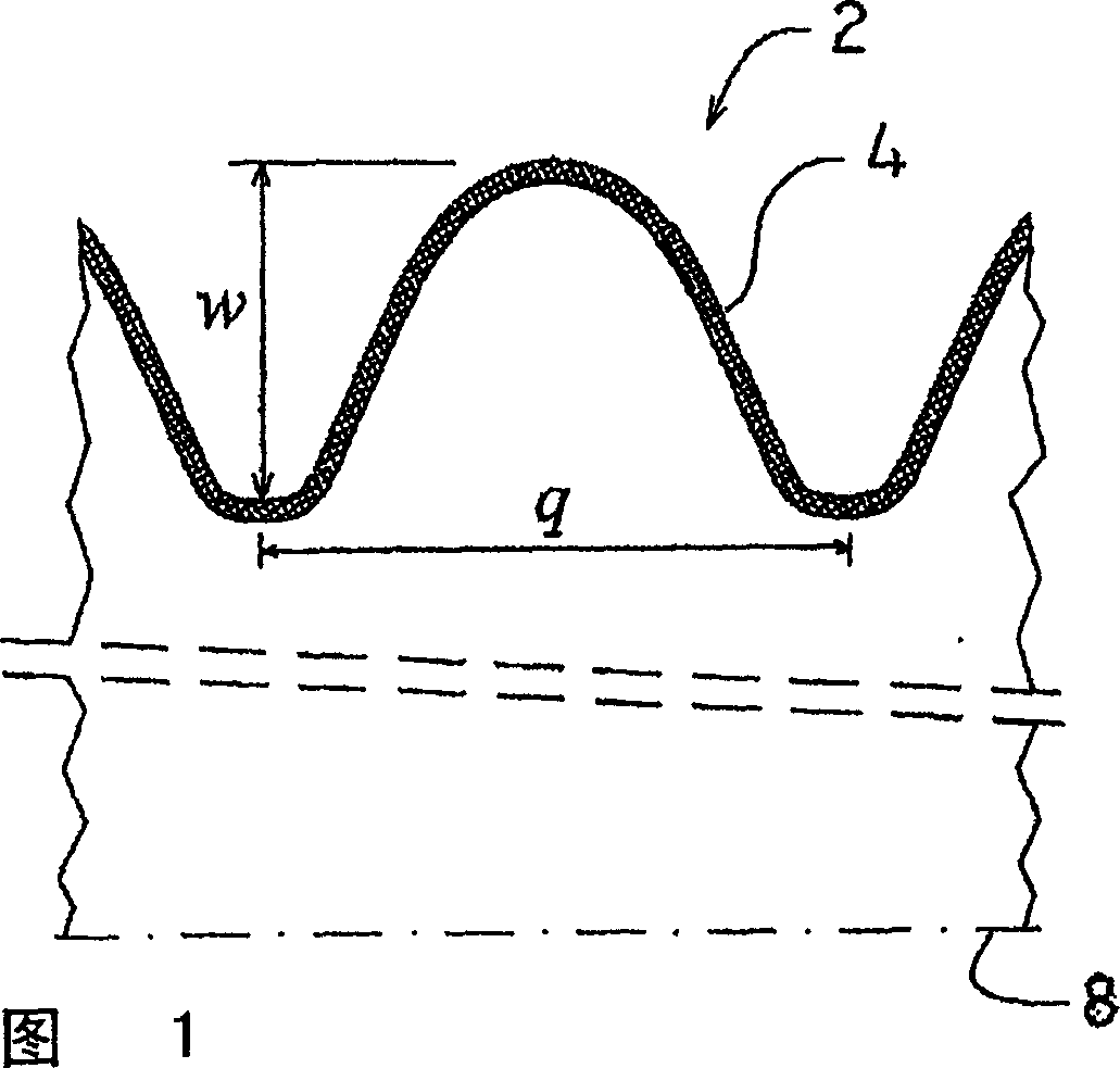
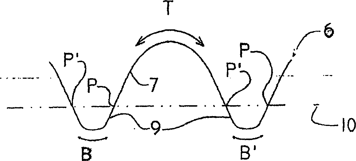
The present invention concerns a flexible, tubular device e.g. a bellows with an internal diameter up to 60 millimeters, said device comprising one or more corrugated convolutions ( 2 ), said convolutions having an overall bell-like shape with rounded top portions (T) and rounded bottom portions (B,B'). The novel aspects involve that the curvature of the outside surface of the convolutions ( 2 ) is numerically smaller at the top portions (T) than at the bottom portions (B,B'), said curvature being derived from a curve ( 6 ) defined as the intersection of the outside surface ( 4 ) of the device and a plane through the longitudinal axis ( 8 ) of the device, as well as they involve that the curvature of said curve changes sign only once at a change position (P,P') located between a top portion (T) and an adjacent bottom portion (B,B''), and that the length of a first section ( 7 ) on the curve ( 6 ) is at least 10% longer than the length of a second section ( 9 ) on the curve, said first section ( 7 ) extending from one change position (P) to an adjacent change position (P') via a top portion (T), and said second section ( 9 ) extending from one change position (P) to an adjacent change position (P') via a bottom portion (B,B'). This provides an improved design with increased durability due to increased flexibility at lower stresses, compared to the prior art.
Description
technical field [0001] The present invention relates to a flexible tubular device having an internal diameter of up to 60 mm, said device comprising one or more undulating surrounds having a general bell-like shape with a rounded top and a rounded bottom. The invention further relates to the use of such devices. Background technique [0002] A flexible tubular device such as a bellows with one or more surrounds imparts a degree of flexibility to a conduit carrying gas, air, water, steam, petrochemicals or any other substance under varying conditions of temperature and pressure. Turbines, pumps, compressors, heat exchangers, reactors and valves are typical types of equipment where bellows are used to absorb the relative motion between the equipment and the connecting piping. Unless some compensation is provided for these dimensional changes, high stresses can be introduced into the equipment or piping and can lead to system failure. The inherent flexibility enables bellows ...
Claims
Login to View More Application Information
Patent Timeline
 Patent Type & AuthorityApplications(China)
IPC IPC(8): F16L11/15F16L27/11
CPCF16L11/15F16L27/11
InventorH·彼得森S·B·奥尔森K·B·尼尔森
OwnerNORSK HYDRO ASA