
Pull disc device for initiating engine

An engine and coil reel technology, applied in the field of puller devices, can solve the problems of manual work, affecting the smoothness of starting the engine 2, small size, etc.

Inactive Publication Date: 2006-03-01
KYMCO
View PDF0 Cites 0 Cited by
  • Summary
  • Abstract
  • Description
  • Claims
  • Application Information

AI Technical Summary

Problems solved by technology

Therefore, the gap between the lock screw 134 and the wire reel 121 is too large, and when the gland 132 or the wire reel 121 rotates, the gland 132 is prone to unsteady up and down deflection and shaking. The two driving levers 131 are affected by the elasticity of the two small springs 133 to produce relatively large up and down vibrations, and the projections 135 of the two driving levers 131 are easily separated from the guide rails 136 of the gland 132. The lever 131 cannot be opened and closed smoothly, which affects the smoothness of starting the engine 2
[0012] 2. The assembly of the second lever 131 is difficult and the labor cost is high:
However, because the two small springs 133 are small in size and easy to bounce, in the process of assembling the two shift levers 131 on the reel 121, the manual work is quite tedious and the assembly difficulty is high, which relatively consumes a large labor cost.

Method used


Image

  • Pull disc device for initiating engine
  • Pull disc device for initiating engine
  • Pull disc device for initiating engine

Examples


Embodiment Construction

[0032] The aforementioned and other technical contents, features and effects of the present invention will be more clearly understood in the following detailed description of a preferred embodiment with reference to the drawings.

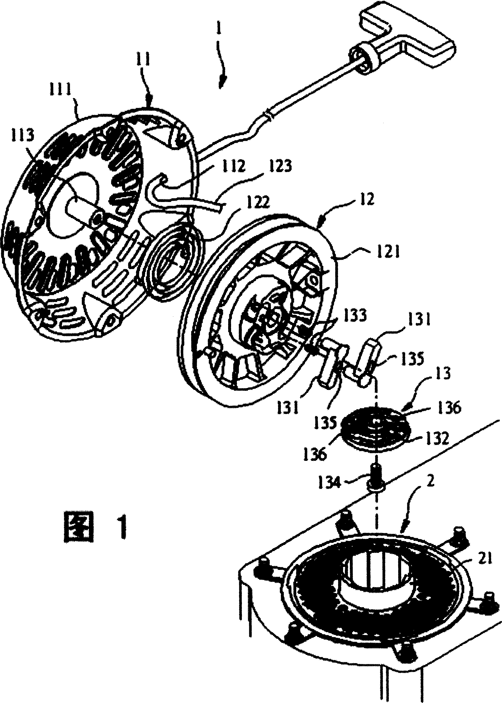
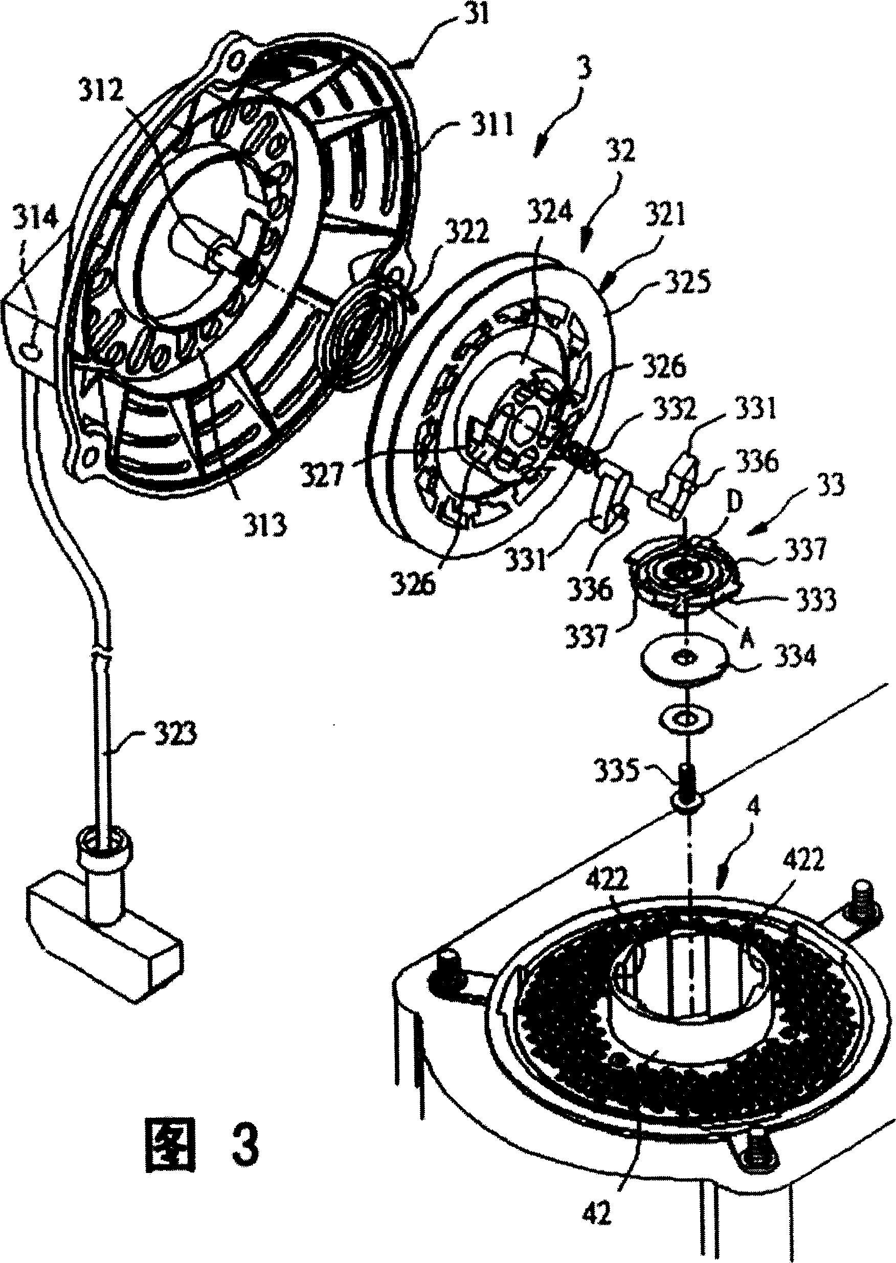
[0033] See Figure 3 with Figure 4, is the preferred embodiment of the pulling device 3 for starting the engine of the present invention. Wherein, the engine 4 includes a starting flywheel 42 , and the inner peripheral surface of the starting flywheel 42 has a plurality of engaging slots 422 spaced apart from each other. The pulling device 3 used for starting the engine comprises an outer cover unit 31 that can be assembled on the starting flywheel 42 of the engine 4, a coil unit 32 that is arranged in the outer cover unit 31, and a coil unit 32 that can receive the coiled wire. The unit 32 drives the driving unit 33 that starts the flywheel 42 to rotate in conjunction with each other. The driving unit 33 is located below the winding unit 32 .

...


PUM


Abstract

The pull disc device for initiating engine includes one string winding unit and one driving unit driven with the string winding unit. The driving unit has two shift rods with guide pin and capable of swinging, one gland to cover the two shift rods, one spacer to hold the gland, and one locking part. The gland has two arced tracks for these two guide pins to stretch in, and these two arced tracks match to form one circle smaller than the spacer. The spacer makes the locking force applied in the great area of the gland homogeneously and evenly, and this ensures the fluent linked motion of the two shift rods in the gland and raises the engine starting efficiency.

Description

【Technical field】 [0001] The invention relates to a puller device, in particular to a puller device for starting an engine. 【Background technique】 [0002] See Figure 1 with figure 2 , a conventional pulling device 1 is used to start an engine 2 . The engine 2 includes a flywheel 21 . The puller device 1 includes a cover unit 11 that can be assembled above the flywheel 21 of the engine 2, a winding unit 12 that is arranged between the cover unit 11 and the flywheel 21, and a flywheel 21 that can be linked. Rotate the starting unit 13. [0003] The pull cover unit 11 has an outer cover 111 forming a cable outlet 112 , and a positioning column 113 extending downward from the center of the outer cover 111 . The wire reel unit 12 has a wire reel 121 rotatably sleeved on the positioning post 113, a wire reel 121 arranged between the wire reel 121 and the outer cover 111 and its two ends are respectively fixed to the wire reel 121. The disc spring 122 on the outer cover 111 a...

Claims


Application Information

Patent Timeline
IPC IPC(8): F02N3/02
Inventor 林苍懋陈瑞田
Owner KYMCO
Learn More