A linear actuator with self-locking spindle

A technology of an actuator and a rotating shaft, which is applied in the field of furniture and can solve problems such as insufficient space for the actuator

Inactive Publication Date: 2006-03-01
LINAK AS
View PDF2 Cites 9 Cited by
  • Summary
  • Abstract
  • Description
  • Claims
  • Application Information

AI Technical Summary

Problems solved by technology

First ruled out the use of air and liquid cooling, partly due to cost issues and partly due to lack of space in the actuator

Method used


Image

  • A linear actuator with self-locking spindle
  • A linear actuator with self-locking spindle
  • A linear actuator with self-locking spindle

Examples


Embodiment Construction

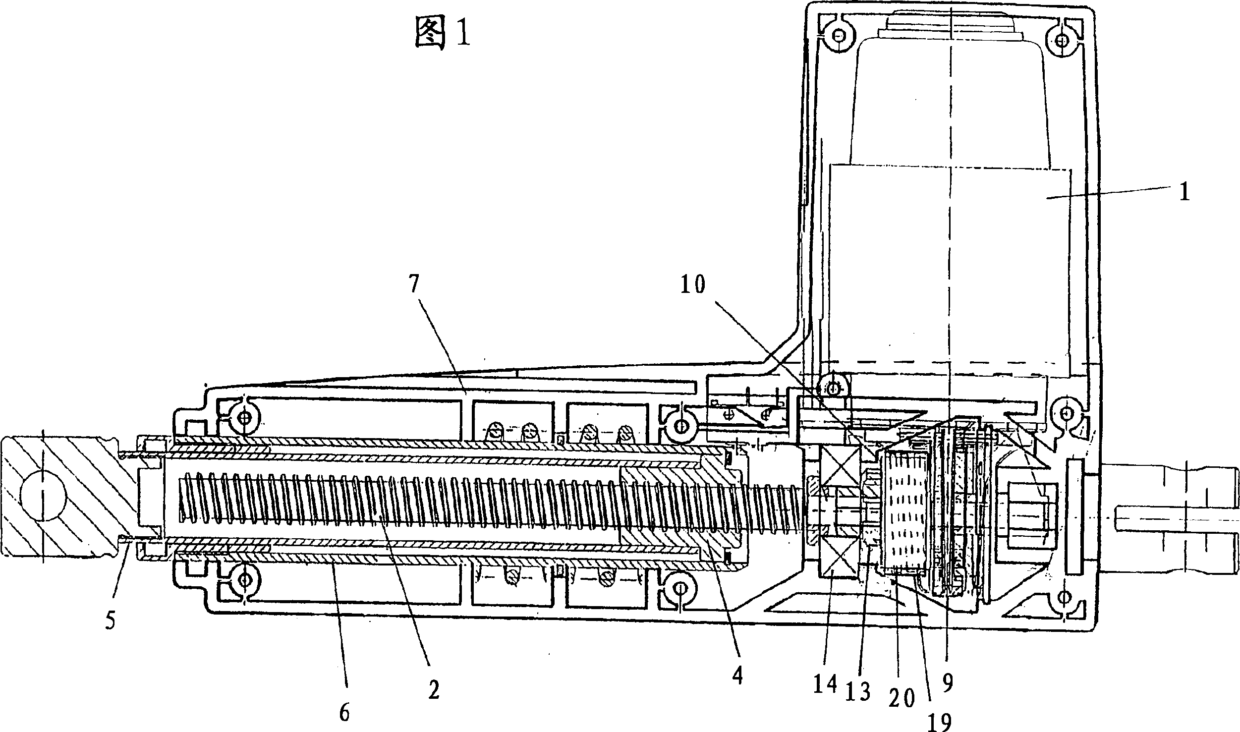
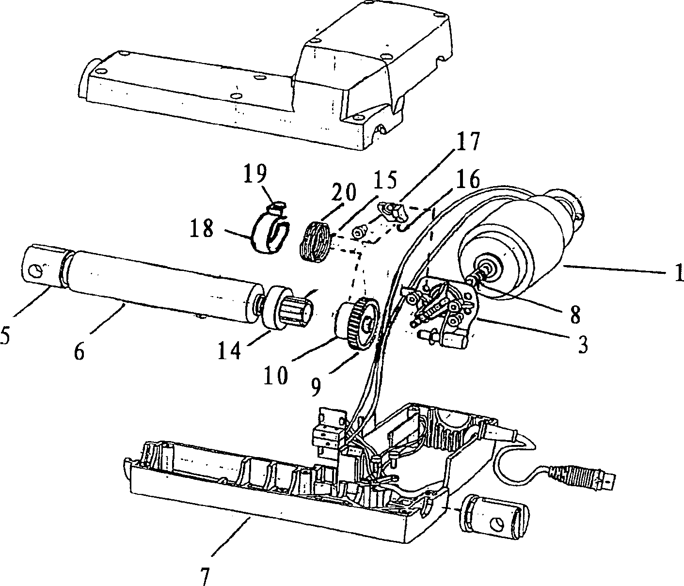
[0014] The linear actuator shown in the figures comprises a reversible low voltage electric motor (DC) 1 which drives a rotating shaft 2 through a worm drive. Reference numeral 3 designates a front part for the motor. A nut 4 is arranged on said shaft and has fixed thereon a drive rod 5 in the form of a tube telescopically arranged in an outer tube 6 embedded in the housing of the actuator 7 in.

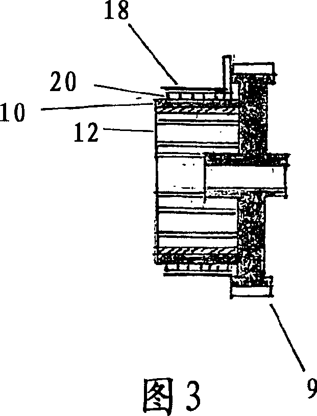
[0015] The worm drive comprises a steel worm 8 formed in the extension of the motor shaft, and a worm wheel 9 with a cylindrical element 10 integrally formed on the side, which houses an insert 12 . The worm gear is made of plastic (POM) fixedly molded on an insert made of light metal (Aluminum Zinc).

[0016] The worm wheel 9 is secured to said shaft by means of a splined coupling where part of the spline is in the insert 12 and the other part is formed by an element 13 fixed on the end of the shaft. The shaft is mounted in a bearing 14 in front of the worm wheel.

[0017] On th...


PUM


Abstract

An actuator, preferably a linear actuator for furniture, comprises a brake spring (20) in the form of a helical spring having a plurality of windings wound around a cylindrical element (10) of plastics rotatable at least during braking, said spring being tightened around the cylindrical element for braking. The frictional heat generated hereby can cause the plastics to be deformed, which adversely affects the braking power. This is solved by providing the cylindrical element (10) consisting of plastics with an insert (12) of metal for carrying off the frictional heat preferably into other metal parts of the actuator that may serve as cooling faces. To carry off heat additionally, it is proposed to arrange a second heat-conducting element (18) in intimate contact with the outer side of the spring (20), said element being likewise connected with other metal parts of the actuator that may serve as cooling faces.

Description

technical field [0001] The invention relates to an actuator, preferably for furniture, comprising a retaining brake spring in the form of a helical spring wound several times around a plastic cylindrical element which is rotatable at least during braking, The spring is tensioned around the cylindrical element for braking. Background technique [0002] EP662573B1 discloses a linear actuator of the type mentioned above. To illustrate the background of the present invention, reference is made to this EP document as figure 2 Example shown. The illustrated actuator is driven by an electric motor which drives a shaft through a worm drive. A nut is arranged on the rotating shaft, and the extension rod is fixed on the nut. The worm is formed in an extension of the motor shaft and is steel. On the worm wheel side as an integral part of the worm wheel there is provided a cylindrical element around which a brake spring is positioned, one end of which is fastened to the motor housi...

Claims


Application Information

Patent Timeline
Patent Type & Authority Applications(China)
IPC IPC(8): F16H25/20F16D41/20F16D65/28F16H25/24
CPCF16H2025/2463F16H25/2454
Inventor J·C·巴斯特霍尔姆K·韦斯特曼
Owner LINAK AS
Why Eureka
Try Eureka