Multifunctional solar building and building community

A solar energy building, multi-functional technology, applied in the field of solar energy utilization, can solve the problems of public space without comfortable temperature, single function, pollution and so on

Inactive Publication Date: 2019-08-16
邱定平
View PDF0 Cites 2 Cited by
  • Summary
  • Abstract
  • Description
  • Claims
  • Application Information

AI Technical Summary

Problems solved by technology

[0003] At present, the known solar buildings have the following problems when adjusting the sunlight to the building: one is that in summer, only a part of the sunlight can be blocked from entering the building, and a large part of the sunlight enters the building. absorbed
Moreover, when the outdoor sunlight is blocked from entering the room in summer, it will cause light pollution. Whether it is using reflective glass or reflective curtains, it will cause light pollution to adjacent buildings or the ground.
The third is that in winter, because there is no suitable thermal energy storage device in the prior art, when the sun is very strong during the day, the indoor temperature is very high, even exceeding the comfortable temperature range required by the human body, and because the temperature difference between indoor and outdoor is too large, indoor The heat energy will be quickly dissipated to the outside, resulting in waste of heat energy, and at night due to the lack of sunlight radiation, the indoor temperature gradually decreases, making it necessary to use electricity or other fossil energy for heating
The fourth is that the existing solar buildings have very poor blocking and utilization effects on the incident sunlight on both sides of the east and west directions. In summer, it will cause serious light pollution and cannot completely block solar light from entering the room, and in winter it cannot make sunlight all shot indoors
Fifth, the function is relatively simple, just to adjust the indoor temperature simply
Seventh, the outdoors of residential buildings are very hot in summer and very cold in winter, and there is no public space with comfortable temperature

Method used


Image

  • Multifunctional solar building and building community
  • Multifunctional solar building and building community
  • Multifunctional solar building and building community

Examples


Embodiment Construction

[0044] The implementation of the present invention adjusts and installs shutters of different structures according to the position and direction of the building relative to sunlight.

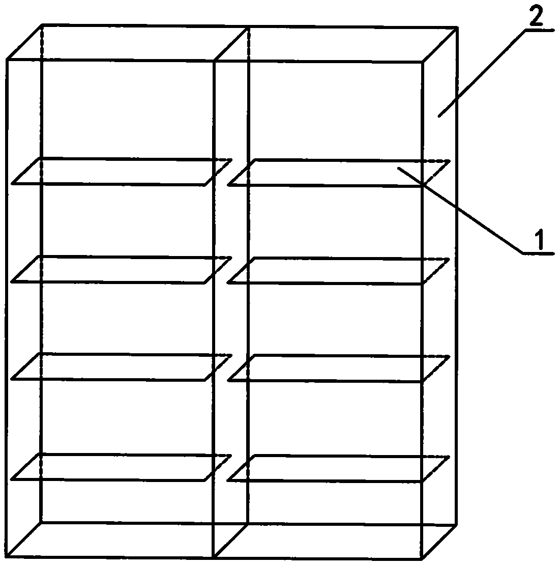
[0045] figure 1 It is a schematic diagram of the louvers of the present invention installed on the south or north wall of any floor, wherein 1 is a louver, and 2 is a reflector, the width of the reflector is slightly larger than the width of the louver, and the louver is installed on the south side of the earth’s northern hemisphere , the shutters for the southern hemisphere are installed on the north side.

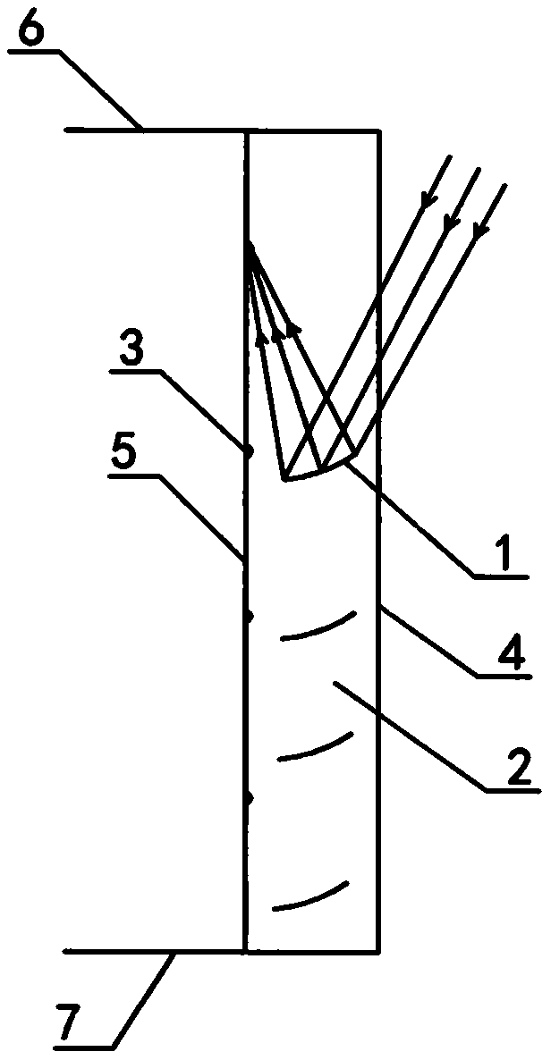
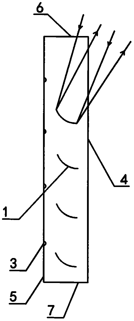
[0046] figure 2 is the above figure 1 The side view of the louvers in the figure, 1 is the louvers in the figure, 2 is the reflector, 3 is the heat collector, 4 is the outer transparent plate, 5 is the inner transparent plate, 6 is the upper floor, and 7 is the floor. The louvers reflect sunlight to the heat collector, which is used to heat the room in winter and cool it in summer.

[...


PUM


Abstract

The invention relates to a multifunctional solar building and a building community. The multifunctional solar building and the building community are technically characterized in that three technicalschemes are separately implemented according to three different directions and positions of the building relative to the sun. Shutters are installed on the roof and the south facing the sun or the north of the building, wherein angles of blades the shutters can be adjusted in the north-south direction; and shutters are installed on the wall body in the east-west direction, wherein angles of bladesthe shutters can be adjusted in the east-west direction and in the north-south direction. Through the shutters, sunlight does not enter the building in summer, or the sunlight is collected for refrigeration or other purposes, while the sunlight is injected into the room or collected for heat storage devices for heating or other purposes in winter.

Description

[0001] Technical field [0002] A multifunctional solar building and a building community of the invention belong to the technical field of solar energy utilization. Background technique [0003] At present, the known solar buildings have the following problems when adjusting the sunlight to the building: one is that in summer, only a part of the sunlight can be blocked from entering the building, and a large part of the sunlight enters the building. absorbed. Moreover, blocking the outdoor sunlight from entering the room in summer will cause light pollution. Whether it is using reflective glass or reflective curtains, the adjacent buildings or ground will be subject to light pollution. The third is that in winter, because there is no suitable thermal energy storage device in the prior art, when the sun is very strong during the day, the indoor temperature is very high, even exceeding the comfortable temperature range required by the human body, and because the temperature di...

Claims


Application Information

Patent Timeline
Patent Type & Authority Applications(China)
IPC IPC(8): E04B1/00E04D13/18E06B9/28E06B9/386F24S23/70F22B1/00F28B1/00A61N5/06
CPCA61N5/0613A61N5/0625A61N2005/0659A61N2005/0661E04B1/00E04D13/00E06B9/28E06B9/386F22B1/006F24S23/70F28B1/00Y02B10/10Y02B10/20Y02E10/40
Inventor 邱定平
Owner 邱定平
Why Eureka
Try Eureka