Conveyor chain

A conveyor chain and chain link technology, applied in the field of conveyor chains, can solve the problems of time-consuming, increased number of parts, etc., and achieve the effects of suppressing wear, prolonging life, and reducing the number of parts

Active Publication Date: 2006-03-08
TSUBAKIMOTO CHAIN CO
View PDF1 Cites 1 Cited by
  • Summary
  • Abstract
  • Description
  • Claims
  • Application Information

AI Technical Summary

Problems solved by technology

[0005] As a kind of conveyor chain, that is, the conventional conveyor belt has a structure in which the first member and the second member are combined to sandwich the ball, so there is a probl

Method used


Image

  • Conveyor chain
  • Conveyor chain
  • Conveyor chain

Examples


Embodiment Construction

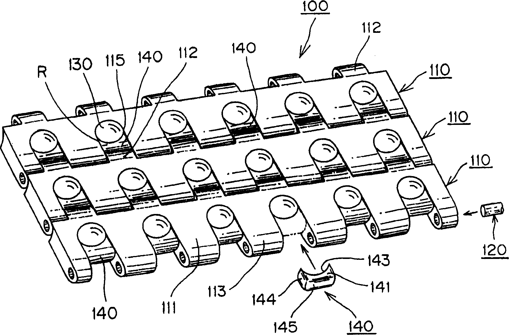
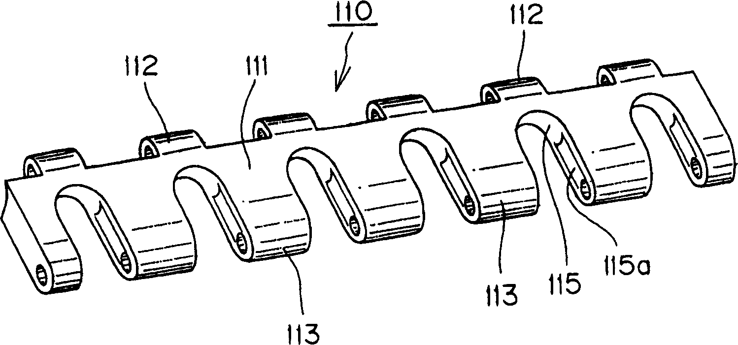
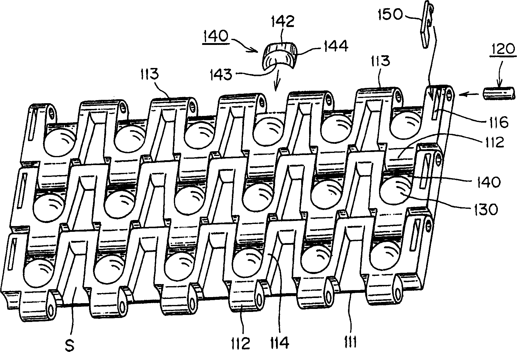
[0018] based on Figure 1 to Figure 7 Examples of the present invention will be described. figure 1 It is a perspective view of a part of the conveyor chain viewed from the surface side, figure 2 It is a perspective view of the link viewed from the surface (conveying surface) side, image 3 It is a perspective view of a part of the conveyor chain viewed from the back side, Figure 4 It is a perspective view of the link viewed from the back side, Figure 5 It is an expanded view of the chain link, (A) is a top view from the side of the conveying surface, (B) is a front view from the arrow X direction of the drawing (A), (C) is a top view from the back side, and (D) is a top view from the drawing (C) The front view of the arrow Y direction, Image 6 It is an explanatory diagram showing an example of the arrangement state of the links constituting the conveyor chain, Figure 7 It is an explanatory diagram showing the operation state of the conveyor chain.

[0019] like fi...


PUM


Abstract

The present invention provides a conveyor chain that can reduce the number of components of the conveyor chain and can easily assemble, disassemble, and take out balls. In the conveyor chain (100) in which the chain links (110) of the article loading part (111) for carrying articles are adjacent to each other and connected in an endless shape with connecting pins, the one side of the aforementioned article loading part (111) is arranged A U-shaped notch (115) having an inner peripheral surface (115a) for clamping the ball is formed between the hinge parts (113), and the chain adjacent to the U-shaped notch (115) faces the The free ball (130) inserted between the hinge part (112) of the joint (110) and the aforementioned U-shaped cutout (115) can rotate by clamping the inner peripheral surface (115a) for the ball and the stopper (140). The upper and lower parts of the free ball (130) respectively protrude from the surface of the object loading part (111) and the lower end of the hinge part (114).

Description

technical field [0001] The present invention relates to a conveyor chain suitable for conveying load box-shaped, plate-shaped and other items whose bottom surface is flat, and particularly relates to a conveyor chain in which the upper and lower parts of a plurality of free balls protrude freely from the upper and lower ends of the conveyor chain respectively. . Background technique [0002] Conveyor belts are known as a type of conveyor chain for conveying loads of articles. A conveyor belt is known in which rotatable balls are installed on belt modules constituting the conveyor belt, and conveyed articles slide laterally to the side of the belt during conveyance and are discharged. (JP-A-2003-182829 Gazette). [0003] The conveyor belt is configured as follows: the belt module for carrying articles is formed by overlapping the first part and the second part up and down, and the hinge parts respectively formed on the first part and the second part are combined to form the ...

Claims


Application Information

Patent Timeline
IPC IPC(8): B65G17/08B65G17/38
CPCB65G17/32B65G17/24B65G17/40
Inventor 尾崎肇芝山胜俊村上吉洋
Owner TSUBAKIMOTO CHAIN CO
Why Eureka
Try Eureka