Linear motor and compressor with same
A linear motor and compression molding technology, applied in the field of compressors, can solve the problems of hindering the vibration magnetic flux, difficult to manufacture the magnetic yoke, and unable to vibrate the body.
- Summary
- Abstract
- Description
- Claims
- Application Information
AI Technical Summary
Problems solved by technology
Method used
Image

Examples
Embodiment 1
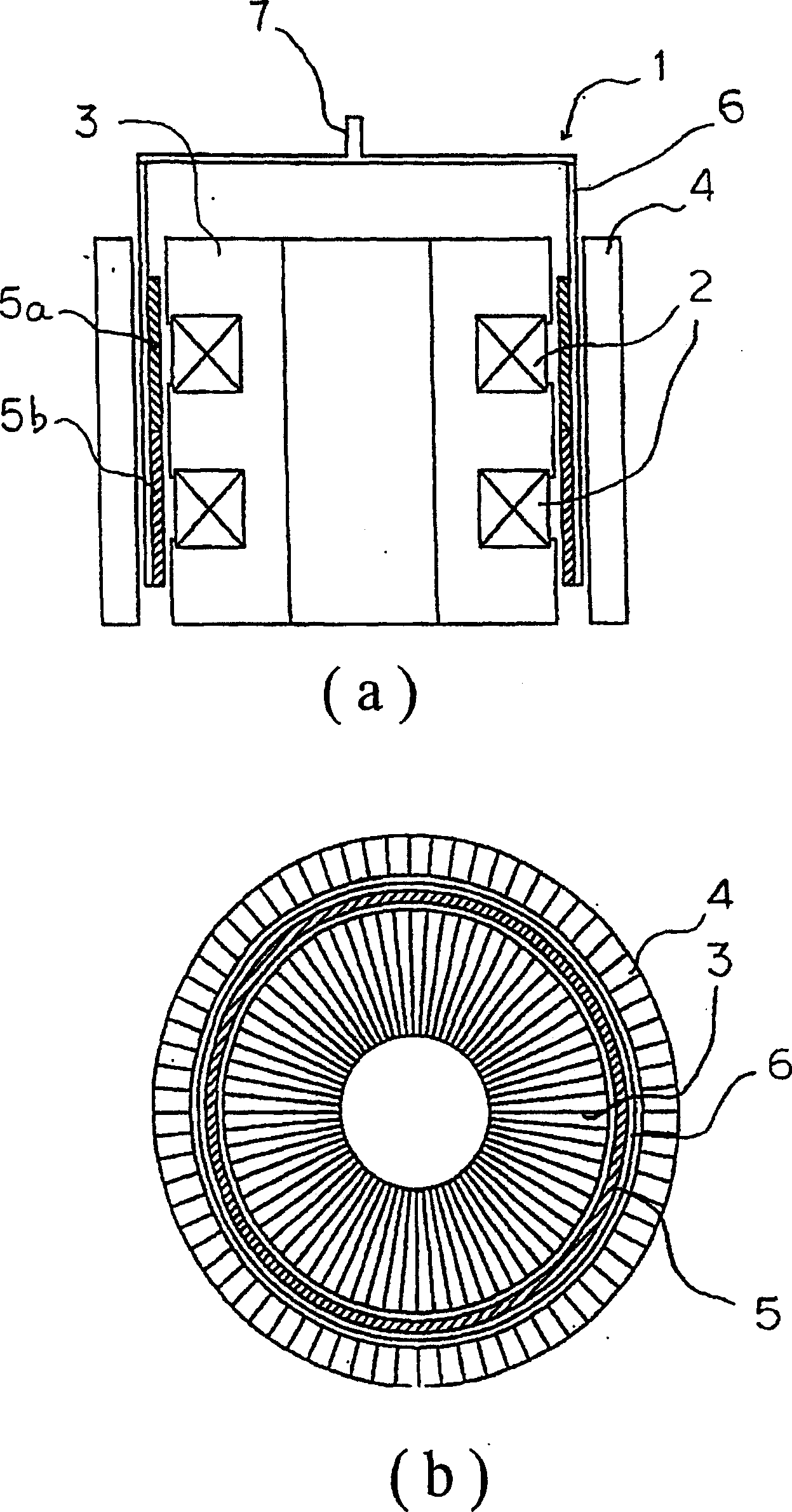
[0014] figure 1 The configuration of the linear motor 1 is shown. The linear motor 1 has a cylindrical inner yoke portion 3, a coil portion 2 wound on the inner yoke portion 3, an outer yoke portion 4 disposed inside the inner yoke portion 3, and a The gap between the outer yoke portion 4, the permanent magnet pieces 5a, 5b vibrating with the magnetic flux generated by the coil portion 2, and the cylindrical vibrating body 6 supporting the permanent magnet pieces 5a, 5b. The permanent magnet pieces 5 a and 5 b are fixed to the side surface of the vibrating body 6 on the inner yoke portion 4 side. At one end of the vibrating body 6, there is an output unit 7 for taking out the vibration of the vibrating body 6 to the outside. The output unit 7 is shaped to cover the cylindrical vibrating body 6 with a cover. In addition, a resonance spring is attached to the output shaft of the output unit 7, and by utilizing the resonance of the spring, the force required for vibration is ...
Embodiment 2
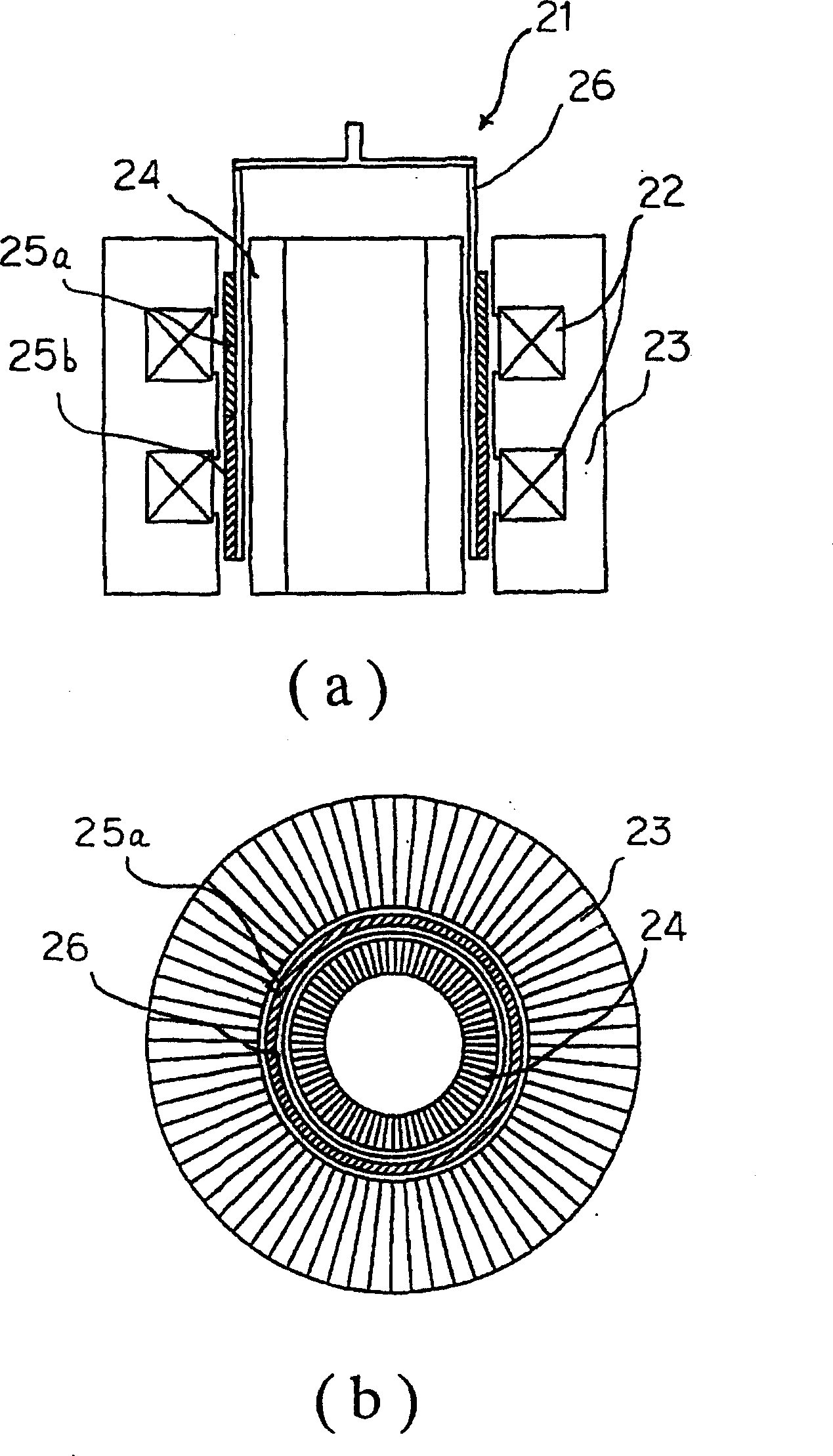
[0031] image 3The shown linear motor 21 includes a cylindrical outer yoke portion 23 having a coil portion 22 wound with a wire, an inner yoke portion 24 located inside the outer yoke portion 23, and an inner yoke portion 24 located inside the outer yoke portion 23 and the inner yoke portion. The gap between the yoke portion 24, the permanent magnet pieces 25a, 25b that vibrate with the magnetic flux generated by the coil portion 22, the vibrating body 26 that supports and fixes the permanent magnet pieces 25a, 25b, and the vibrating body that fixes the permanent magnet pieces 25a, 25b 26 is located between the permanent magnet pieces 25 a , 25 b and the inner yoke portion 24 . The vibrating body 26 has magnetism. In addition, the inner yoke part 24 and the outer yoke part 23 are formed by laminating electromagnetic steel in a circumferential shape.
[0032] According to the above configuration, the gap between the outer yoke portion 23 and the inner yoke portion 24 can be ...
Embodiment 3
[0035] Figure 4 The configuration of the linear motor 31 is shown. The linear motor 31 has a cylindrical inner yoke portion 33, a coil portion 32 that winds a wire around the inner yoke portion 33, an outer yoke portion 34 that arranges the inner yoke portion 33 inside, and is located in the inner magnetic field. The gap between the yoke portion 33 and the outer yoke portion 34 , the permanent magnet piece 35 vibrating with the magnetic flux generated by the coil portion 32 , and the cylindrical vibrating body 36 supporting the permanent magnet piece 35 . The permanent magnet piece 35 is fixed to the side surface of the vibrating body 36 on the inner yoke portion 33 side. At one end of the vibrating body 36, there is an output unit 37 for taking out the vibration of the vibrating body 36 to the outside. The output unit 37 is shaped to cover the cylindrical vibrating body 36 with a cover.
[0036] The linear motor will be described in detail below.
[0037] The inner yoke ...
PUM
 Abstract
Description
Claims
Application Information
 - R&D Engineer
- R&D Manager
- IP Professional
- Industry Leading Data Capabilities
- Powerful AI technology
- Patent DNA Extraction
Browse by: Latest US Patents, China's latest patents, Technical Efficacy Thesaurus, Application Domain, Technology Topic.
© 2024 PatSnap. All rights reserved.Legal|Privacy policy|Modern Slavery Act Transparency Statement|Sitemap