Surface acoustic wave device and process for fabricating the same

a surface acoustic wave and wave signal technology, applied in piezoelectric/electrostrictive transducers, generators/motors, transducer types, etc., can solve the problems of adversely affecting device characteristics, difficult to provide advanced measures to reduce unnecessary wave signals, and wave signals, etc., to suppress the propagation of unnecessary waves and improve the performance of the device

Active Publication Date: 2006-12-12
SKYWORKS PANASONIC FILTER SOLUTIONS JAPAN
View PDF13 Cites 25 Cited by
  • Summary
  • Abstract
  • Description
  • Claims
  • Application Information

AI Technical Summary

Benefits of technology

[0007]In view of the problems residing in the prior art, it is an object of the present invention to provide a surface acoustic wave device that enables to improve performance of the device by suppressing propagation of an unnecessary wave.
[0009]In the above arrangement, the plurality of grooves are formed in the back surface of the piezoelectric substrate. Since the grooves extend in the direction intersecting with the propagating direction of the surface acoustic wave, unlike an arrangement that grooves extend substantially parallel to the propagating direction of the surface acoustic wave, this arrangement enables to increase the degree of variance of reflection of the surface acoustic wave (unnecessary wave) that has been sent from the transmitting electrode of the comb transducer and reached the back surface of the substrate. Thus, there is no or less likelihood that the unnecessary wave reflected on the grooves may be received by the receiving electrode of the comb transducer, and the surface acoustic wave device exhibits good device characteristics with less or no noise.
[0010]There is likelihood that a surface acoustic wave of a specific wavelength may be selectively reflected depending on the interval (pitch) of the adjoining grooves if the interval (pitch) of the adjoining grooves is identical among the grooves, even if the grooves substantially extend in the direction interesting with the propagating direction of the surface acoustic wave. In view of this, preferably, the grooves are formed in such a manner that the interval of the adjoining grooves is decreased as the groove extends from one end of the surface acoustic wave device toward the other end thereof, wherein the one end and the other end are each located on a side substantially perpendicular to the propagating direction of the surface acoustic wave. This arrangement enables to maximize the degree of variance of reflection of the unnecessary wave with respect to all the possible wavelengths, thereby effectively suppressing adverse effects of the unnecessary wave.
[0012]The above arrangement enables to maximize the degree of variance of reflection of the unnecessary wave on the back surface of the piezoelectric substrate, and realize a surface acoustic wave device capable of effectively suppressing adverse effects of the unnecessary wave. Further, since the grinding technique is employed, a thick affected layer in which crystalline structure of the substrate is modified by a stress applied to the substrate in forming the plurality of grooves is formed in a region on the back side of the piezoelectric substrate. Since the unnecessary wave is reflected at random in the affected layer, adverse effects of the unnecessary wave can be effectively suppressed.

Problems solved by technology

The unnecessary wave signal may adversely affect device characteristics if being received by the receiving electrode.
Therefore, the reflecting conditions of the unnecessary wave to the respective grooves are identical to each other, which makes it difficult to provide advanced measures for reducing the unnecessary wave signal.

Method used


Image

  • Surface acoustic wave device and process for fabricating the same
  • Surface acoustic wave device and process for fabricating the same
  • Surface acoustic wave device and process for fabricating the same

Examples


Embodiment Construction

[0023]In the following, preferred embodiments of the present invention are described referring to the accompanying drawings. Throughout the specification and the claims, a surface of a piezoelectric substrate which is opposite to a surface where electrodes are formed, and in which grooves are formed is referred to as “a back surface of the substrate”.

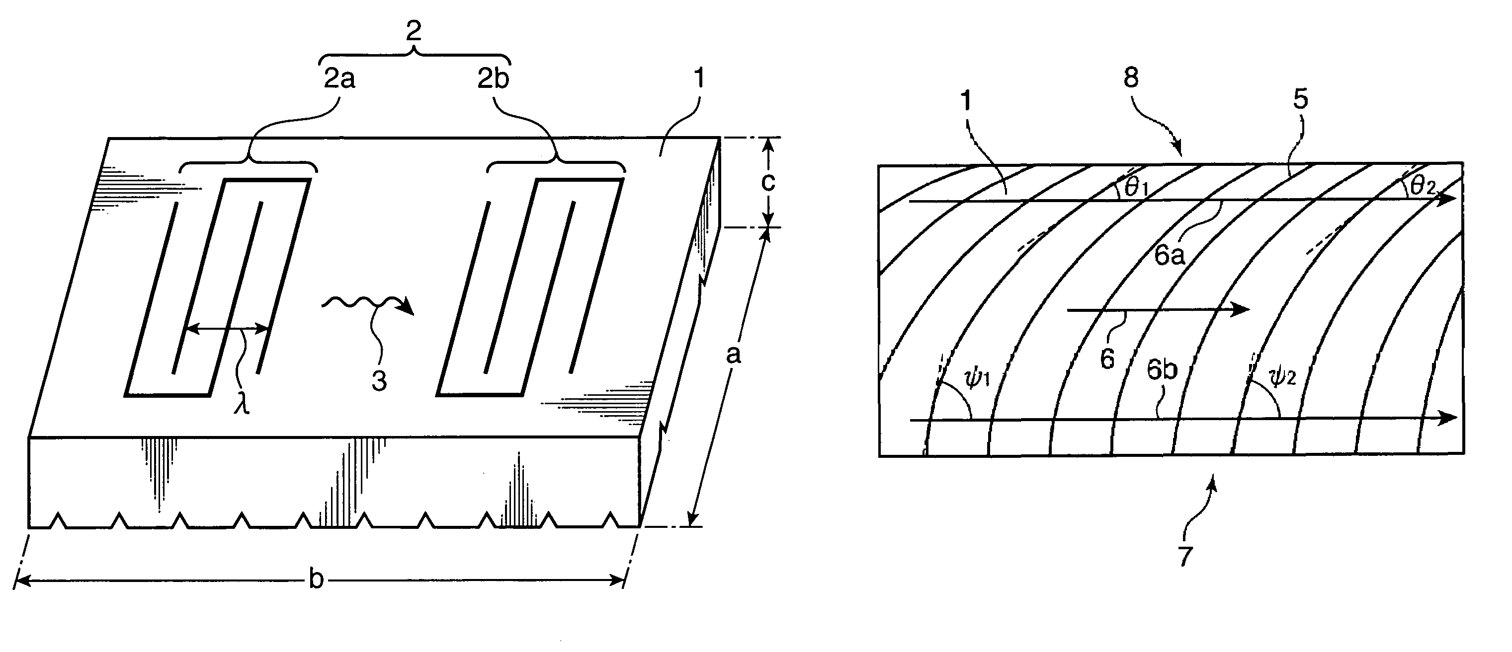
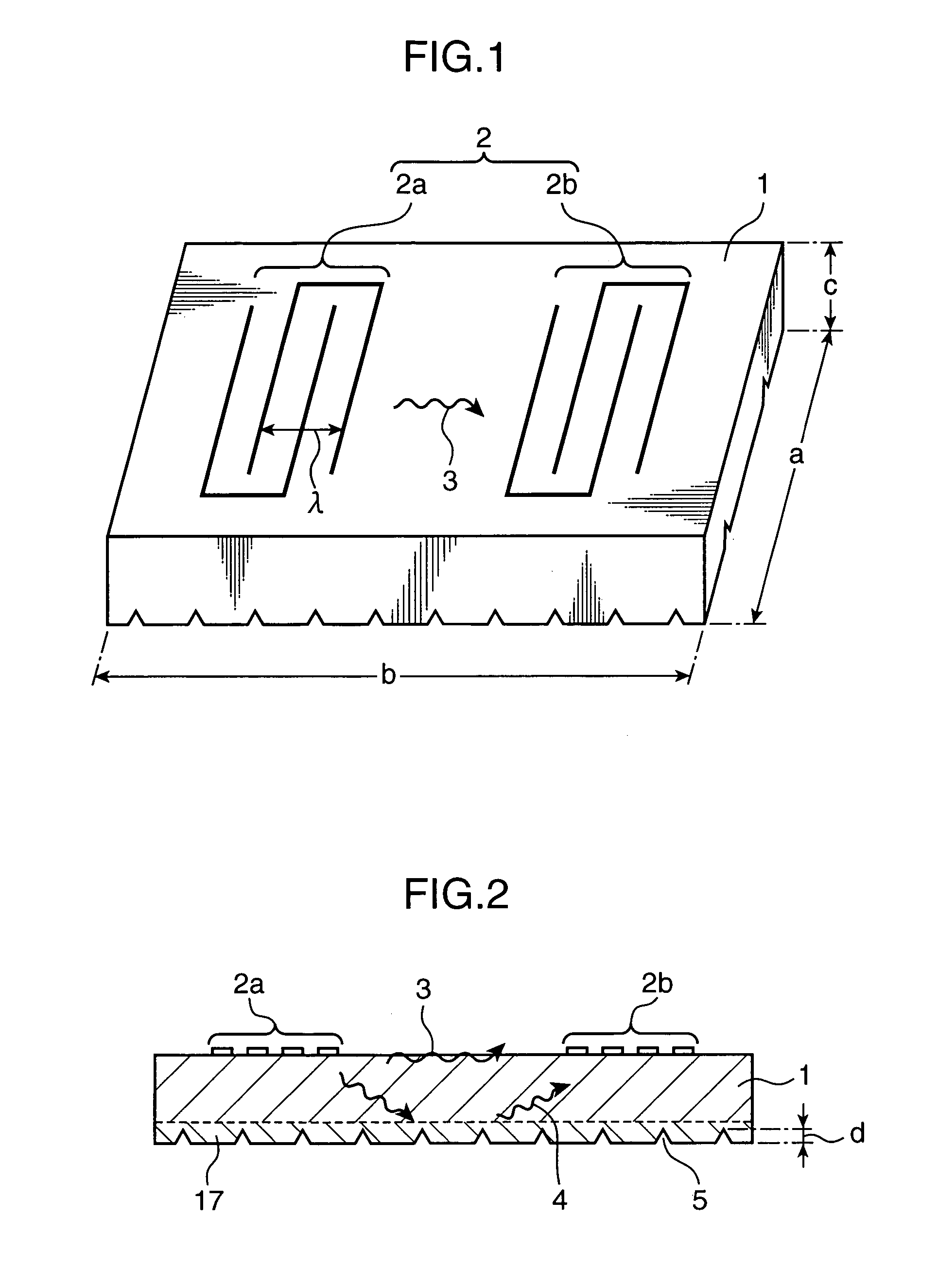
[0024]FIG. 1 is a perspective view of a surface acoustic wave filter as an example of a surface acoustic wave device embodying the invention. As shown in FIG. 1, the acoustic surface wave filter is constructed such that electrode pairs 2a and 2b constituting a comb transducer 2 are arranged opposing to each other on a piezoelectric substrate 1 made of LiTaO3 or LiNbO3 in a propagating direction of a surface acoustic wave 3. The surface of the piezoelectric substrate 1 is distorted by an electrical signal inputted to the electrode pair 2a on a transmitting side (hereinafter, called as “transmitting electrode 2a”), and the distortion is p...


PUM

PropertyMeasurementUnit
thicknessaaaaaaaaaa
thicknessaaaaaaaaaa
thicknessaaaaaaaaaa

Abstract

A surface acoustic wave device has a piezoelectric substrate 1, and a comb transducer 2 formed on a surface of the piezoelectric substrate 1. Grooves 5 for eliminating an unnecessary wave are formed in a back surface of the surface acoustic wave device in such a manner that the interval of the adjoining grooves 5 is decreased as the groove 5 extends from one end 7 of the piezoelectric substrate 1 to the other end 8 thereof. With this arrangement, angles defined by the extending directions of the respective grooves 5 and the propagating direction of the surface acoustic wave can be differentiated from each other, and the reflecting conditions of the unnecessary wave to the respective grooves 5 can be varied from each other. This arrangement enables to improve characteristics of the surface acoustic wave device.

Description

BACKGROUND OF THE INVENTION[0001]1. Field of the Invention[0002]The present invention relates to a surface acoustic wave device, and a process for fabricating the same.[0003]2. Description of the Related Art[0004]Generally, a surface acoustic wave device such as a surface acoustic wave (SAW) filter has a comb transducer comprised of an electrode pair on a transmitting side (simply called as “transmitting electrode”) and an electrode pair on a receiving side (simply called as “receiving electrode”) on a surface of a piezoelectric substrate. The transmitting electrode and the receiving electrode each has a pair of electrodes constructed such that an anode and a cathode intersect with each other. A surface acoustic wave excited by the transmitting electrode is propagated over the surface of the piezoelectric substrate, and is received by the receiving electrode for output.[0005]In the piezoelectric substrate constituting the surface acoustic wave device, there is a wave other than the ...

Claims


Application Information

Patent Timeline
Patent Type & Authority Patents(United States)
IPC IPC(8): H03H9/64H03H3/08H03H9/25H03H9/02
CPCH03H3/08H03H9/02622Y10T29/42H03H9/64H03H9/25
Inventor TAKANO, ATSUSHI
Owner SKYWORKS PANASONIC FILTER SOLUTIONS JAPAN
Why Eureka
Try Eureka