
Floor joint fastening grooving

A joint lock and floor technology, applied in the direction of floors, buildings, building structures, etc., can solve the problems of low tensile strength and high installation requirements, and achieve the effects of improved tensile strength, less deformation and collapse, and simple installation.

Inactive Publication Date: 2006-03-29
李卫
View PDF0 Cites 7 Cited by
  • Summary
  • Abstract
  • Description
  • Claims
  • Application Information

AI Technical Summary

Problems solved by technology

[0003] In order to overcome the disadvantages of low tensile strength and high installation requirements of the existing floor joint lock tongue and groove, the purpose of the present invention is to provide a floor joint lock tongue and groove, which is easy to produce and easy to construct. and high tensile strength

Method used


Image

  • Floor joint fastening grooving
  • Floor joint fastening grooving
  • Floor joint fastening grooving

Examples


Embodiment Construction

[0018] The present invention will be further described below in conjunction with the accompanying drawings and embodiments.

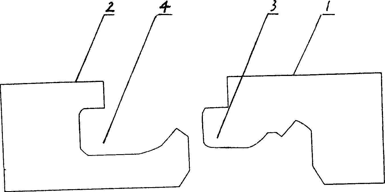
[0019] figure 1 Shown is an embodiment of the floor joint lock tongue and groove of the present invention, which includes two identical rectangular floor sheets I1 and rectangular floor sheets II2, on one side of each rectangular floor, and below the top surface, There is a groove 4 inward along its length direction, and a tenon 3 is arranged outward at the corresponding position on the other side of the floor. The shape, size and position of the groove 4 and the tenon 3 are all adapted , The groove 4 and the tenon 3 are inlaid to form a lock between the two floors, and the two floors are tightly combined. In this embodiment, the groove 4 is a rectangular groove, and the lower edge of the groove extends outward and obliquely upward to form a tenon 6; the tenon 3 is a rectangular tenon corresponding to the groove 4, The lower edge of the tenon extends ...


PUM


Abstract

On one side of every rectangular floor board, along its length direction an inward recessed groove is cut, on the correspondent position of another side of said floor board an outward tongue is set, the forms, sizes and positions of said recessed groove and tongue must be adapted, between two floor boards the inlaying joint of recessed groove and tongue can be used for forming locking fastener. The lower groove edge of the recessed groove is extended outward and toward oblique upper direction to form hook tongue, and lower tongue edge of the tongue is extended inward and toward oblique upper direction to form hook groove, the forms, sizes and positions of hook tongue and hook groove must be adapted. Said invention utilizes the inlaying joint of recessed groove and tongue and inlaying joint of hook tongue and hook groove to make the floor boards be firmly and tightly combined together.

Description

technical field [0001] The invention relates to a floor pavement structure, in particular to a floor joint lock tongue and groove for assembling two adjacent floor sheets. Background technique [0002] Existing floor lock tongue and groove can be roughly divided into two classes, and flat push type installation groove and bottom surface form 45 degree angles to embed and then push down and install groove and groove. The installation of these two types of floor grooves requires the use of tools to install, and the requirements for the flatness of the ground are very high. The height difference within the range of 3 square meters cannot exceed 3 mm. The request is impossible to fulfill. Moreover, the tensile strength of the flat-push tongue and groove is relatively low, and the highest can reach 500kg / lM, which cannot meet the needs of the market. Contents of the invention [0003] In order to overcome the disadvantages of low tensile strength and high installation require...

Claims


Application Information

Patent Timeline
Patent Type & Authority Applications(China)
IPC IPC(8): E04F15/02
Inventor 李卫
Owner 李卫
Learn More