Indoor unit for air conditioner

A technology for air conditioners and indoor units, which is applied in the field of indoor units, and can solve the problems of increased flow resistance at the upper part of the inner side of the indoor unit, and achieve the effects of minimized flow resistance, reduced overall height, and simple structure

Inactive Publication Date: 2006-03-29
LG ELECTRONICS (TIANJIN) APPLIANCES CO LTD
View PDF0 Cites 9 Cited by
  • Summary
  • Abstract
  • Description
  • Claims
  • Application Information

AI Technical Summary

Problems solved by technology

[0010] However, in the air conditioner indoor unit of the prior art, since only the front side of the indoor unit is provided with the discharge ports 6 and 8, the air after heat exchange is vertically turned and sent directly to the front of the discharge ports 6 and 8 at the inner upper part of the indoor unit. , so the flow impedance of the upper part inside the indoor unit increases, and because the exhaust air from the outlets 6 and 8 is sent straight forward, it takes a long time for the exhaust air to diffuse in the up, down, left and right directions of the room.

Method used


Image

  • Indoor unit for air conditioner
  • Indoor unit for air conditioner
  • Indoor unit for air conditioner

Examples


Embodiment Construction

[0046] In order to further understand the invention content, characteristics and effects of the present invention, the following examples are given, and detailed descriptions are as follows in conjunction with the accompanying drawings:

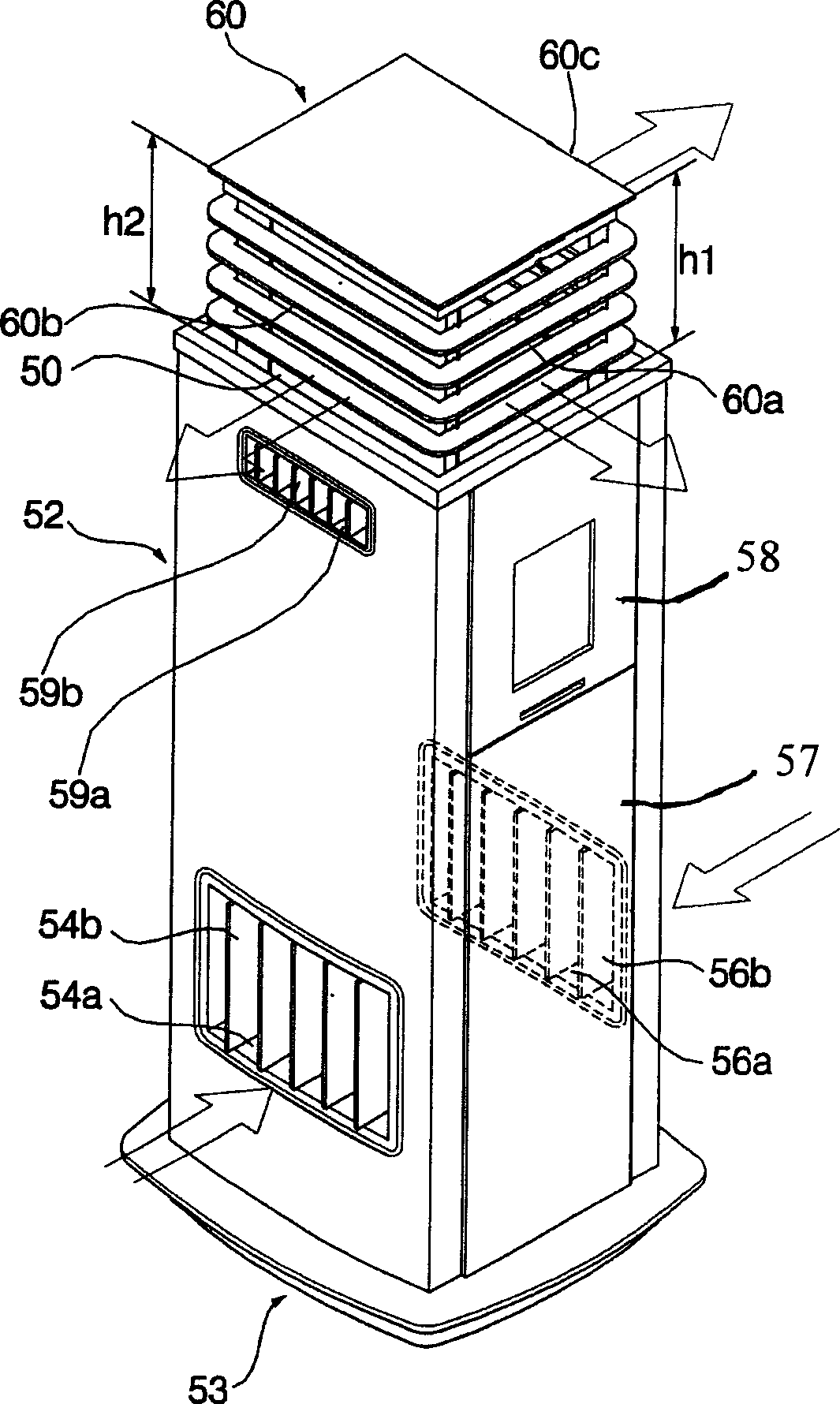
[0047] figure 1 is an oblique view of the air conditioner in operation according to the present invention.

[0048] Air conditioner of the present invention such as figure 1 As shown, it includes a casing 52 formed with a discharge 50 on the upper part;

[0049] The casing 52 has an open upper surface to form a discharge 50 and an open bottom surface in the shape of a square barrel, and is placed on the chassis 53 and fixed to the chassis 53 by fastening screws or the like.

[0050] The casing 52 has left and right suction ports 54a, 56a for sucking air and suction grills 54b, 56b for protecting the left and right suction ports 54a, 56a respectively at the bottom of the left and right sides.

[0051] The outlet unit 60 includes a front o...


PUM


Abstract

The indoor machine of air conditioner includes external shell whose upper portion is formed into discharge outlet, discharge outlet component which can be up-down movably mounted on the external shell and can be lifted toward upper side of discharge outlet and lifting and falling device which can make the lifting amplitude of front face portion of discharge outlet component be relatively larger than that of its back face portion when the discharge outlet component is lifted and fallen.

Description

technical field [0001] The present invention relates to an indoor unit of an air conditioner, in particular to an indoor unit of an air conditioner capable of quickly adjusting the temperature of the indoor air by diffusing and discharging the conditioned air in all directions. Background technique [0002] Generally speaking, an air conditioner is a device that uses a refrigerant refrigeration cycle composed of a compressor, a condenser, an expansion mechanism, and an evaporator to cool / heat the room and purify the air in order to provide users with a more comfortable indoor environment. [0003] Figure 7 is an oblique view of an air conditioner in the prior art in operation, Figure 8 is an oblique view of an air conditioner in the prior art when its operation is stopped, Figure 9 It is an exploded oblique view of the air conditioner front panel in the prior art in a separated state. [0004] Indoor units of conventional air conditioners such as Figure 7 to Figure 9 ...

Claims


Application Information

Patent Timeline
Patent Type & Authority Applications(China)
IPC IPC(8): F24F1/00F24F13/06
Inventor 金江永
Owner LG ELECTRONICS (TIANJIN) APPLIANCES CO LTD
Why Eureka
Try Eureka