Elevator control method

A technology of elevators and control methods, applied in the field of elevator landing control, can solve problems such as inability to apply elevator drives, complex solutions, and difficulties, and achieve simple and reliable adjustments

Inactive Publication Date: 2006-03-29
KONE CORP
View PDF0 Cites 4 Cited by
  • Summary
  • Abstract
  • Description
  • Claims
  • Application Information

AI Technical Summary

Problems solved by technology

However, the solution disclosed in this bulletin is rather complex and, therefore, cannot be applied to all lift drives
[0005] However, when torque control is used in an elevator, since the torque control determines the total torque of the system, it becomes difficult to walk along the reference speed
Increasing the gain increases the torque, but this causes stability issues

Method used


Image

  • Elevator control method
  • Elevator control method

Examples


Embodiment Construction

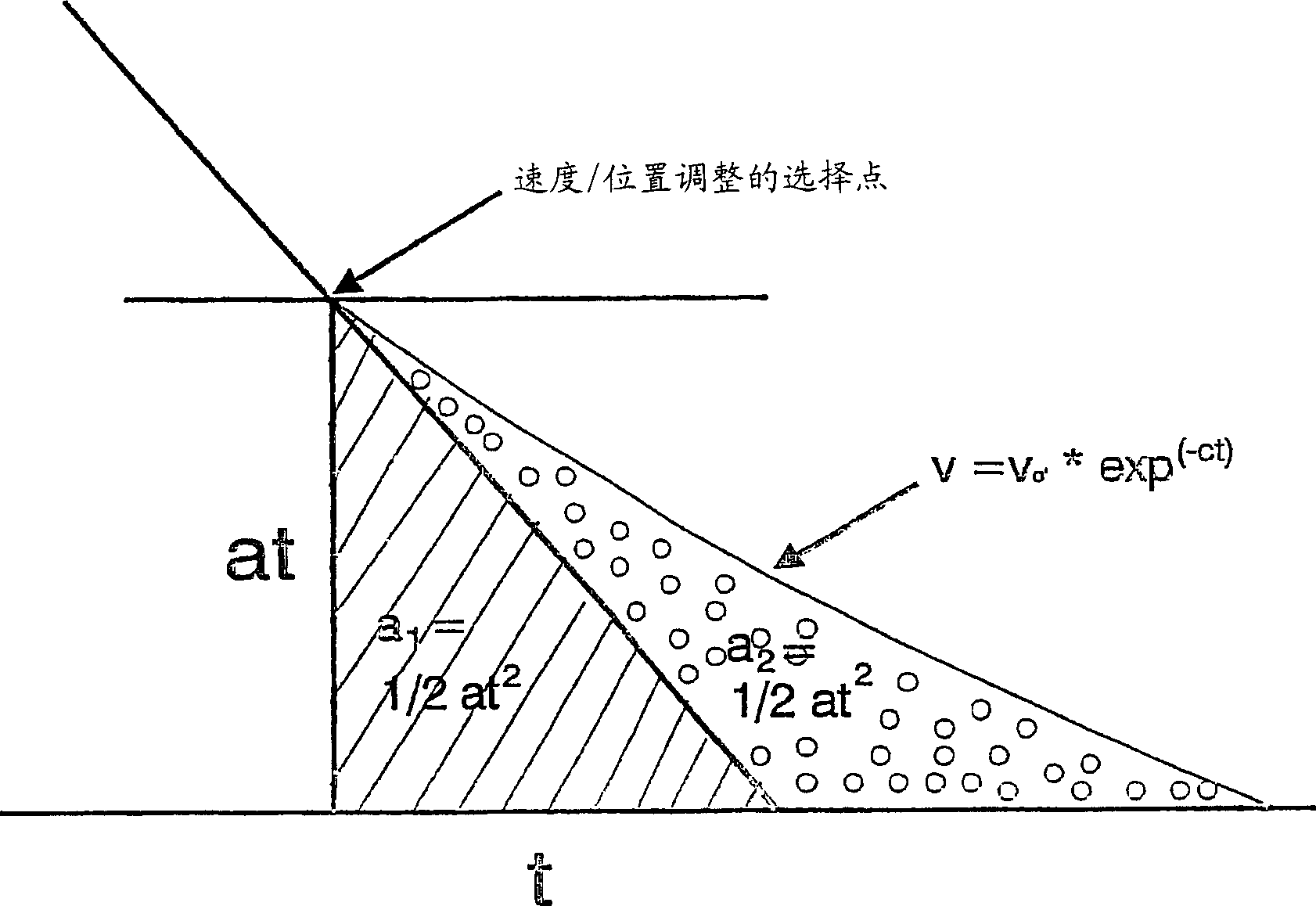
[0016] according to figure 1 , in normal operation, the elevator travel curve includes initial acceleration, constant acceleration phase, constant speed phase, constant deceleration phase, and final deceleration. During the deceleration phase, the speed of the lift etc. decreases deceleratedly, which in figure 1 V of medium speed curve a Partial representation. In the constant deceleration phase, it is well known that the equation v 1 =a*t 1 applied to velocity, where a is the deceleration and t is time, and the equation s 1 =1 / 2*a*t 1 2 Applied to the distance. In other words, when an elevator etc. comes to a decelerated stop, at time t 1 traveled within s 1 =1 / 2*a*t 1 2 distance. If, at the end of the deceleration phase, a final completion phase is added to the velocity profile, in this case the rate of change of the deceleration, that is, the deceleration rate is constant, and the value of the deceleration rate is chosen such that the stop double the distance, ...


PUM


Abstract

A elevator control method wherein the elevator motor is controlled in such manner that the velocity of the elevator follows a speed reference. When the elevator is decelarating, the motor is controlled by a speed adjustment method during the initial decelaration phase, and during the final decelaration phase the motor is controlled by a position adjustment method. The instant of transition from speed adjustment to position adjustment is determined substantially by means of the elevator speed curve.

Description

technical field [0001] The invention relates to an elevator control method as defined in the preamble of claim 1 and an apparatus for controlling an elevator as defined in the preamble of claim 5 . Background technique [0002] In the advanced AC elevator drive, the motor is generally controlled by a frequency converter, and the frequency converter is used to adjust the torque and speed of the motor. Each lift trip can be considered to consist of departure, acceleration, constant velocity portion, deceleration, and stop at the landing point. A reference speed is usually used to control the motor so that the elevator follows a predetermined speed profile as precisely as possible. An important task in elevator operation is to stop the elevator car exactly at the landing point without sudden changes in speed or without moving the car in the opposite direction. [0003] Typically, a constant deceleration is used when the elevator is about to stop and, just before stopping, the...

Claims


Application Information

Patent Timeline
Patent Type & Authority Applications(China)
IPC IPC(8): B66B1/40
CPCB66B1/40
Inventor 佩卡·杰科南
Owner KONE CORP
Why Eureka
Try Eureka