Multiuser detection of differing data rate signals

A technology of data signal and data detection device, applied in the direction of transmission system, electrical components, etc., can solve problems such as the impossible realization of joint channel demodulation and decoding technology

Inactive Publication Date: 2006-03-29
INTERDIGITAL TECH CORP
View PDF0 Cites 0 Cited by
  • Summary
  • Abstract
  • Description
  • Claims
  • Application Information

AI Technical Summary

Problems solved by technology

This makes joint channel demodulation and decoding almost impossible

Method used


Image

  • Multiuser detection of differing data rate signals
  • Multiuser detection of differing data rate signals
  • Multiuser detection of differing data rate signals

Examples


Embodiment Construction

[0014] Hereinafter, a wireless transmit / receive unit (WTRU) includes without limitation a user equipment, a mobile station, a fixed or mobile subscriber unit, a pager, or any other device capable of operating in a wireless environment type. Hereinafter, a base station includes, without limitation, a base station, a class B node (Node-B), a node controller, an access point, or any other bordering device in a wireless environment. Although an FDD wireless system is mentioned in the background section, the following embodiments are applicable to many wireless systems, provided that the high data rate operation and the low data rate operation are transmitted within a shared frequency spectrum.

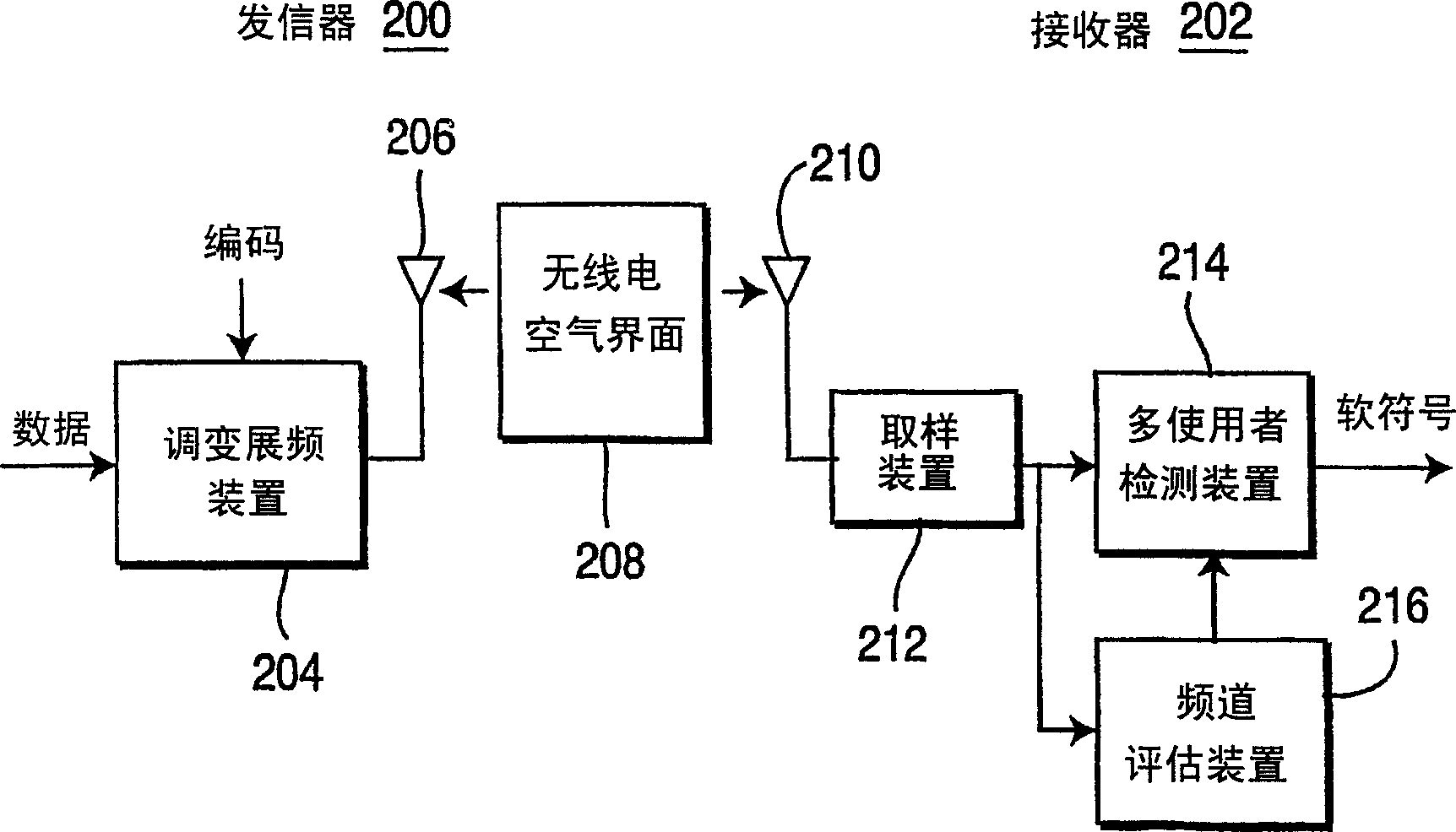
[0015] figure 2 One embodiment of a multi-user detector for use in a wireless communication system operating in accordance with the present invention is depicted. A transmitter 200 and a receiver 202 communicate with each other via a radio air interface 208 . Transmitter 200 may be loc...


PUM


Abstract

A first detector receives a received signal and extracts the data signals from the received signal. A hard decision converter converts soft symbols outputted by the first detector into hard symbols. An interference canceller extracts the voice signals from the received signal. A second detector is connected to the output of the interference canceller, and extracts the individual voice signals. The second detector is a different detector type than the first detector.

Description

technical field [0001] The present invention relates to a wireless communication network, and more particularly to multi-user detection in a frequency division multitasking system. Background technique [0002] signal as figure 1 The frequency division multiplexing (FDD) mode shown transmits, for example, a plurality of voice signals (V1, V2 and V3) and a plurality of data signals (D1 and D2). The voice signal is usually transmitted at a lower power than the data signal because the voice signal can be transmitted at a lower data rate (eg with a higher spreading factor) without significant loss of signal quality. For example, a speech signal may be transmitted with a spread spectrum signal coefficient of 64 (64 chips per data bit), while a data signal may be transmitted with a spread spectrum of 4 chips per data bit due to the higher transmission rate. frequency transmission. like figure 1 As shown, several voice and data signals can be transmitted in the same frequency s...

Claims


Application Information

Patent Timeline
IPC IPC(8): H04B1/69H04B1/707H04B1/713
CPCH04B2001/71077H04B1/71055H04B2201/70705H04B1/7103
Inventor 亚力山大·瑞茨尼克艾利拉·蔡拉费堤·欧兹鲁特利昂德·卡萨凯费许
Owner INTERDIGITAL TECH CORP
Why Eureka
Try Eureka