Partition plate structure of hermetic compressor

A compressor and isolation plate technology, which is applied in mechanical equipment, machines/engines, liquid fuel engines, etc., can solve problems such as impact noise, scratches, fluid leakage, etc., and achieve the effect of preventing impact noise and scratches

Inactive Publication Date: 2006-04-05
LG ELECTRONICS (TIANJIN) APPLIANCES CO LTD
View PDF0 Cites 0 Cited by
  • Summary
  • Abstract
  • Description
  • Claims
  • Application Information

AI Technical Summary

Problems solved by technology

Therefore, when the blades (6A) (6B) pass by, there will be a slight seam phenomenon, resulting in fluid leakage and impact noise
There will also be a problem that the intersecting surface scratches the contact surface of each blade (6A) (6B) or the bearing surface of the bearing bracket (3A) (3B)

Method used


Image

  • Partition plate structure of hermetic compressor
  • Partition plate structure of hermetic compressor
  • Partition plate structure of hermetic compressor

Examples


Embodiment Construction

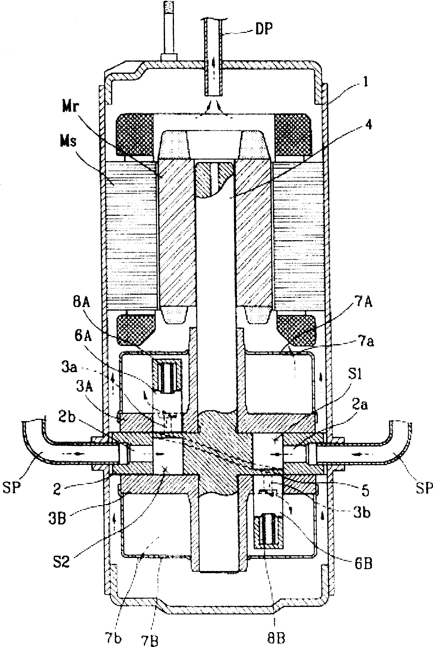
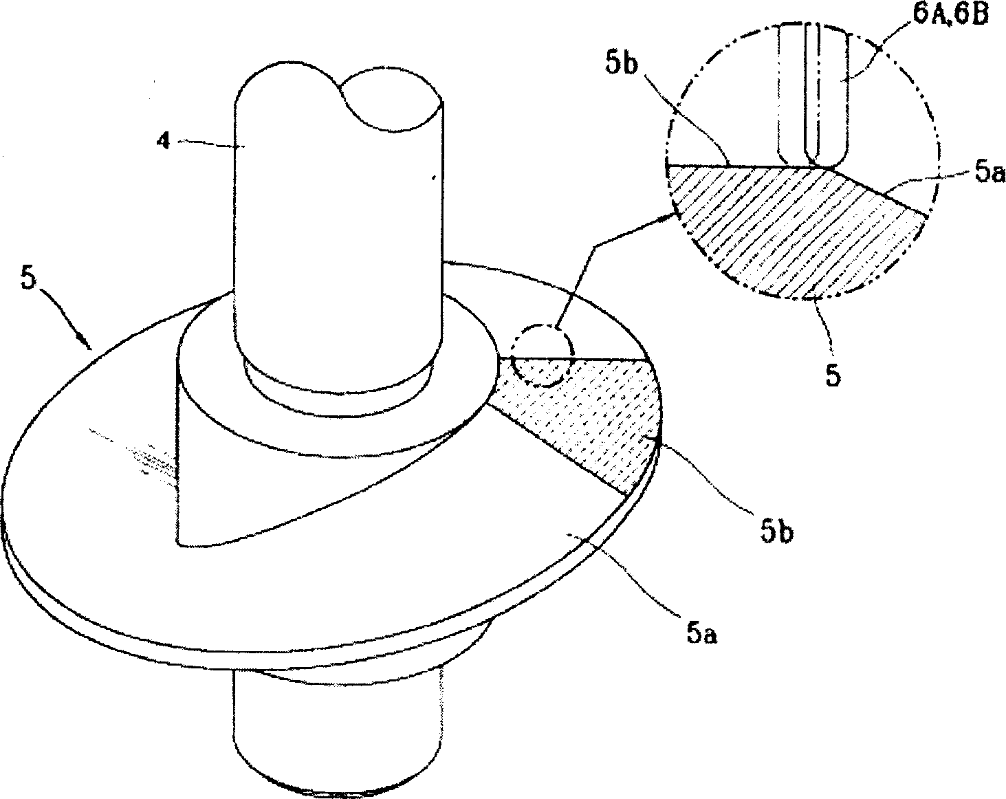
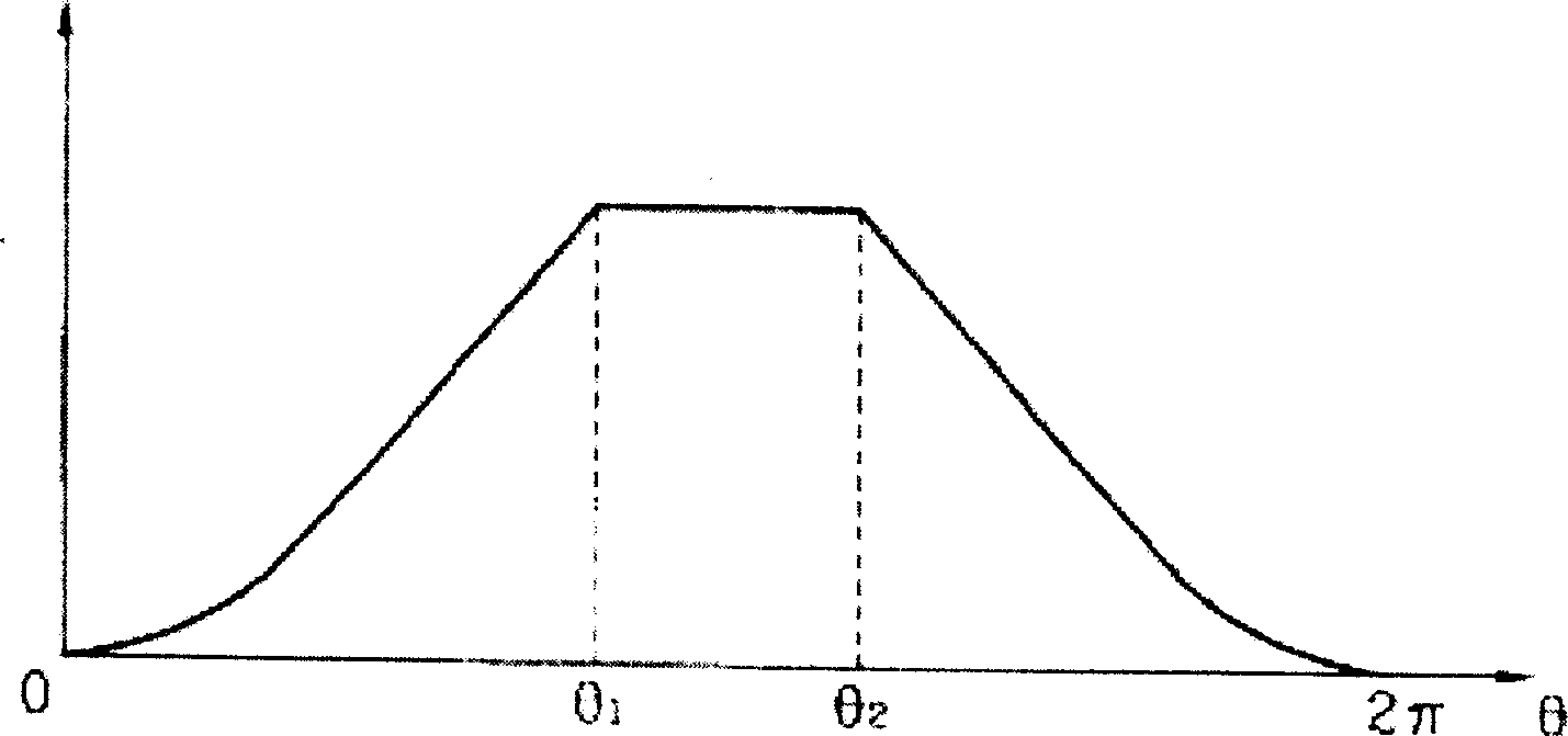
[0025] Hereinafter, the separator plate structure of the hermetic compressor of the present invention will be described in detail using the drawings, Figure 4 It is an oblique view showing the isolation plate of the hermetic compressor of the present invention, Figure 5 It is a schematic diagram showing the coordinate development of the cam surface of the separator plate of the hermetic compressor of the present invention.

[0026] As shown in the figure, the hermetic compressor equipped with the separator plate according to the present invention includes, fixed on the shell ( figure 1 Shown in) (1) The lower half of the cylinder ( figure 1 shown in) (2); the first bearing bracket ( figure 1 shown in )(3A) and the 2nd bearing bracket ( figure 1 shown in) (3B); connected with the rotor (Mr) of the motor mechanism part and connected with each bearing bracket (3A, 3B) at the same time, the rotating shaft (4) that transmits the power of the motor mechanism part to the compres...


PUM


Abstract

The invention discloses a sealed compressor segregation barrier structure, which comprises the following parts: intake, outlet, two sealed space in the cylinder to segregate the cylinder into at least, sealed compressor segregation barrier to exchange the segregated space into intake and compressive domain when two laterals and blade impact and revolve, which contains curved face of specific function curve on two laterals of touching blade. The segregation barrier concludes curved face and point of inflection with plane face around. The flexion is formed by connecting the curved face and plane face, which prevents the impaction noise between blade and segregation barrier in advance. Otherwise, the arc connection is formed between the segregation barrier and plane face, which avoids the bearing face fish tail on the bearing stand.

Description

technical field [0001] The present invention relates to the invention of the isolation plate structure of the compressor. In particular, the invention relates to the invention of the separator plate structure of the hermetic compressor which connects the flat part at the top dead center on both sides of the separator plate to the other curved surface in a curved manner. Background technique [0002] Generally, vane compressors set the linear motion vane in contact with the rotating body and isolate the inner space of the cylinder into the suction area and the compression area. When the rotating body is driven, the phase difference of the rotating body is used to continuously switch the suction area and the compression area. A device that sucks fluid in and compresses it out. [0003] figure 1 It is a longitudinal sectional view showing a conventional hermetic compressor. [0004] As shown in the figure, the original compressor is composed of a motor mechanism part compose...

Claims


Application Information

Patent Timeline
IPC IPC(8): F04C29/06F04C29/00F04C18/00
Inventor 杨广植师范东
Owner LG ELECTRONICS (TIANJIN) APPLIANCES CO LTD
Why Eureka
Try Eureka