Chemical diffusion system, chemical diffusion apparatus, chemical diffusion unit and chemical cartilage

A chemical and equipment technology, applied in the field of chemical diffusion system, can solve the problems of not being widely used, time-consuming installation and operation, etc.

Inactive Publication Date: 2006-04-19
SEIKO EPSON CORP
View PDF3 Cites 15 Cited by
  • Summary
  • Abstract
  • Description
  • Claims
  • Application Information

AI Technical Summary

Problems solved by technology

This causes the problem that the installation operation becomes time-consuming due to the large number of allocators usually required to be installed
However, there are not many insect sex pheromones that have been checked for their mixed affinity
Therefore, traditional spray-type chemical diffusion equipment cannot be widely used

Method used


Image

  • Chemical diffusion system, chemical diffusion apparatus, chemical diffusion unit and chemical cartilage
  • Chemical diffusion system, chemical diffusion apparatus, chemical diffusion unit and chemical cartilage
  • Chemical diffusion system, chemical diffusion apparatus, chemical diffusion unit and chemical cartilage

Examples


Embodiment 1

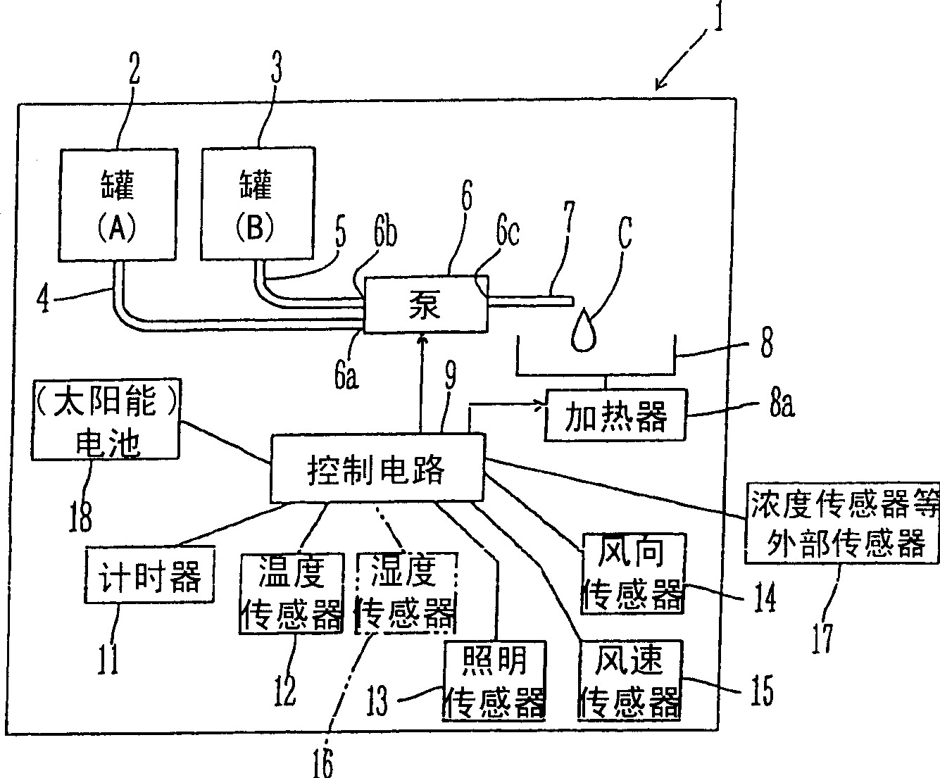
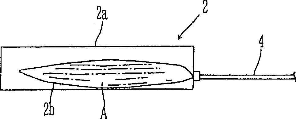
[0075] FIG. 1 is a schematic diagram showing the structure of a chemical diffusion apparatus suitable for dispersing chemicals such as communication disruptors and attractants in a greenhouse or the like. The chemical diffusion device 1 includes a first container 2 filled with a volatile chemical A and a second container 3 filled with a volatile chemical B. Containers 2 and 3 are filled with chemicals A and B in solid or liquid state. The chemicals A and B are supplied from the containers 2 and 3 to the suction holes 6 a and 6 b of the discharge volume variable pump 6 through the chemical supply passages 4 and 5 . Each chemical sucked into the pump 6 is mixed inside the pump 6 and then discharged from the discharge pipe 7 connected to the discharge hole 6c of the pump 6 . The mixed chemicals C are discharged from the discharge pipe 7 onto the evaporation pan 8 serving as a diffusion device. The mixed chemicals C discharged onto the evaporation pan 8 are naturally diffused. ...

Embodiment 2

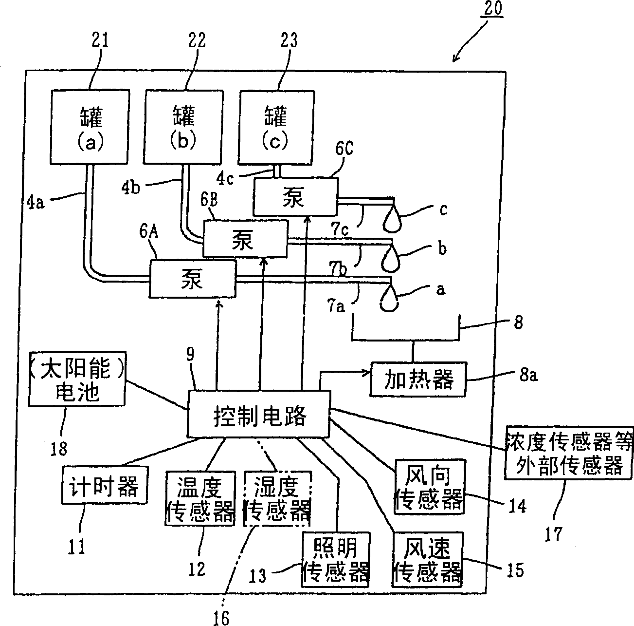
[0084] figure 2 is a schematic diagram showing the structure of a chemical diffusion device according to Embodiment 2. The chemical diffusion apparatus 2 includes a first container 21, a second container 22, and a third container 23, the first to third containers shown serving as chemical containers and filled with chemicals a, b, and c different in composition, respectively. Three pumps 6A to 6C are provided for sucking the corresponding chemicals a to c through the chemical supply passages 4a to 4c, respectively, and discharging the corresponding chemicals a to c from the discharge pipes 7a to 7c. The chemicals a to c are discharged onto the common evaporation pan 8 from the respective discharge pipes 7 a to 7 c. The control circuit 9 is arranged to be able to independently control the driving of the respective pumps 6A to 6C. Descriptions of structures other than the above structures are omitted because they are the same as those of the chemical diffusion apparatus 1 sho...

Embodiment 3

[0092] FIG. 4( a ) is a schematic diagram showing the structure of a chemical diffusion device according to Embodiment 3. FIG. The basic structure of the chemical diffusion device 30 of Embodiment 3 is the same as that of the chemical diffusion device 1 shown in FIG. 1 . Accordingly, corresponding components are denoted by the same reference numerals and descriptions of these components are omitted.

[0093] The chemical diffusion device 30 includes a belt conveyor type diffusion device instead of an evaporation pan. That is to say, the chemical diffusion device 30 includes a belt conveyor 32 and a driving mechanism 33 for driving the belt conveyor 32, the belt conveyor 32 is provided with an endless belt 31, and the endless belt 31 has a structure such as Surface material of felt or sponge. The mixed chemical C is discharged from the discharge pipe 7 onto the endless belt 31 . When the belt conveyor 32 is driven, the endless belt 31 carrying the mixed chemical C moves alon...


PUM


Abstract

A chemical diffusion apparatus ( 1 ) comprises a first tank ( 2 ) filled up with a volatile chemical A such as a communication disturbance agent and a second tank ( 3 ) filled up with a volatile chemical B. The chemicals A and B are sucked by means of a discharge volume variable pump ( 6 ) to be discharged onto an evaporating dish ( 8 ) through a discharge tube ( 7 ). A mixed chemical C discharged onto the evaporating dish 8 is naturally diffused in the air. A control circuit ( 9 ) controls drive of the pump ( 6 ). An input side of the control circuit ( 9 ) is connected to a timer ( 11 ) and an environment parameter detecting means such as a temperature sensor ( 12 ), an illumination sensor ( 13 ), a wind direction sensor ( 14 ) and a wind velocity sensor ( 15 ). The control circuit ( 9 ) controls discharge and discharge volume of the mixed chemical C from the pump ( 6 ) on the basis of detecting results from the respective sensors in accordance with a control program.

Description

technical field [0001] The present invention relates to a chemical diffusing system, chemical diffusing equipment, chemical diffusing unit and chemical cartridges for diffusing chemicals such as communication disruptors and attractants for pests, the chemicals including insect sexual information white. Background technique [0002] There have been known methods of exterminating pests by diffusing attractants such as insect sex pheromones into the air so as to cause communication disturbance of insects for reducing the number of eggs laid and thereby reducing the growth of pests in farms and the like, instead of using pesticides. For example, a method is known in which a large number of insect sex pheromone dispensers are installed in a predetermined space within a cultivation field facility for naturally diffusing insect sex pheromones. In this method, sex pheromones are put into plastic tubes that are hooked on branches of cultivated plants or frames of plastic greenhouse...

Claims


Application Information

Patent Timeline
Patent Type & Authority Applications(China)
IPC IPC(8): A01M1/02A01M1/20A01M7/00A01M5/04A01N63/00
Inventor 伊藤清志山田学
Owner SEIKO EPSON CORP
Why Eureka
Try Eureka