Dust collecting apparatus for vacuum cleaner

A technology for dust collectors and vacuum cleaners, applied in suction filters and other directions, can solve problems such as inconvenience in use, affecting the smoothness of airflow in and out, and achieve the effect of extending maintenance cycles and improving convenience.

Inactive Publication Date: 2006-04-26
TSANN KUEN CHINA ENTERPRISE
View PDF0 Cites 4 Cited by
  • Summary
  • Abstract
  • Description
  • Claims
  • Application Information

AI Technical Summary

Problems solved by technology

[0002] In the prior art, although the structure of the vacuum cleaner is various, the principle of its use is roughly the same, that is, the motor is used to drive the fan blades to rotate to generate suction, so that the air near the suction port passes through an internal dust collecting device. Then it is discharged from the air outlet. Some of the above-mentioned dust collecting devices are in the form of dust collecting bags, and some are containers with at least one dust collecting space. The position of the air outlet, this situation will affect the smoothness of the air flow in and out. Therefore, even if there is still room for dust in the dust bag or dust collection space, the user must replace it frequently if the air outlet is severely blocked. Dust bags, or cleaning containers with dust collection space, are inconvenient to use

Method used


Image

  • Dust collecting apparatus for vacuum cleaner
  • Dust collecting apparatus for vacuum cleaner
  • Dust collecting apparatus for vacuum cleaner

Examples


Embodiment Construction

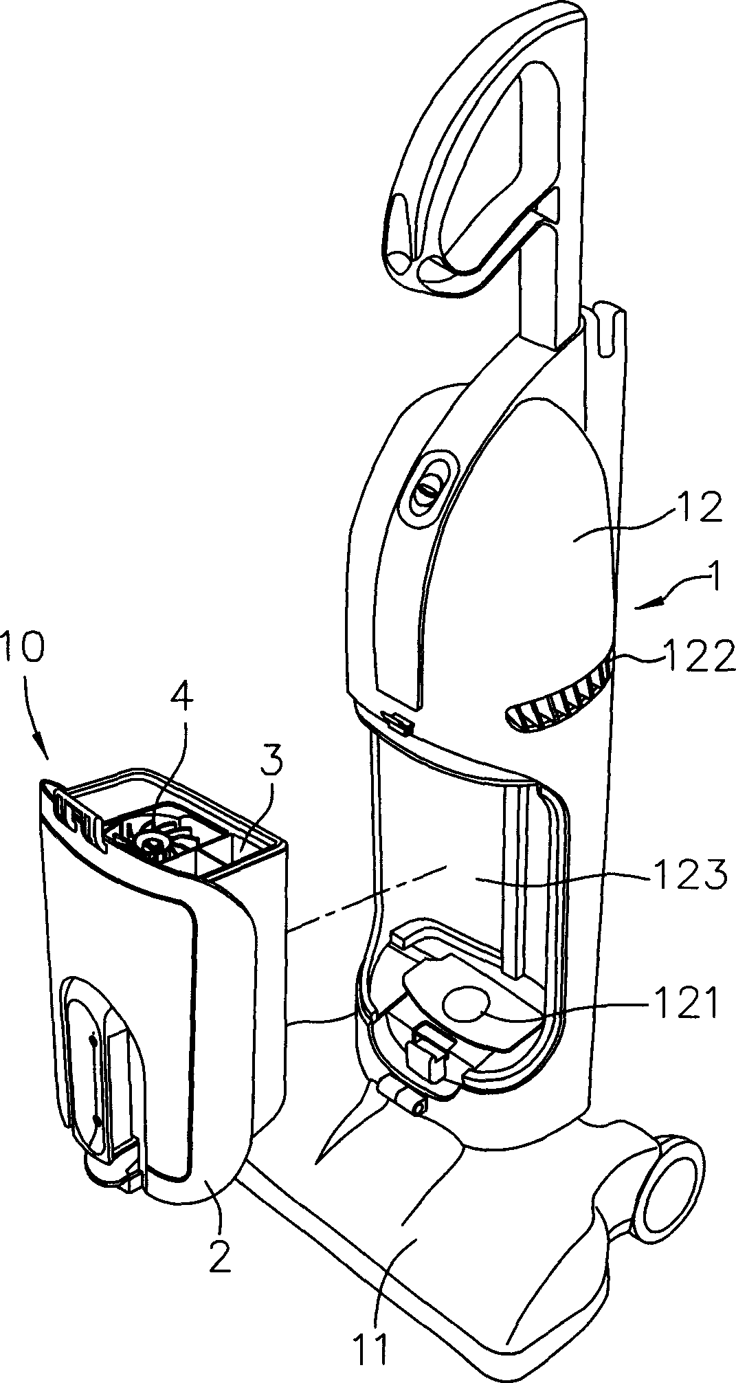
[0017] Refer to figure 1 , 2 3. The first preferred embodiment of the dust collecting device 10 of the present invention is installed on the upright vacuum cleaner body 1. The vacuum cleaner body 1 includes: a dust collector 11 that can move on the ground, and a pivotable The handle 12 is installed above the dust suction part 11, and a motor installed in the handle 12 but not shown in the figure. The motor provides suction so that the dust on the ground below the dust suction part 11 can be After entering an air suction port 121 of the handle portion 12, it is discharged from an air outlet 122 of the handle portion 12. An assembly chamber 123 is recessed between the air suction port 121 and the air outlet 122 of the handle portion 12 In terms of design, the assembly chamber 123 only needs to be located on the path of the air flow in and out, and it is not necessary to be provided on the handle portion 12 in implementation.

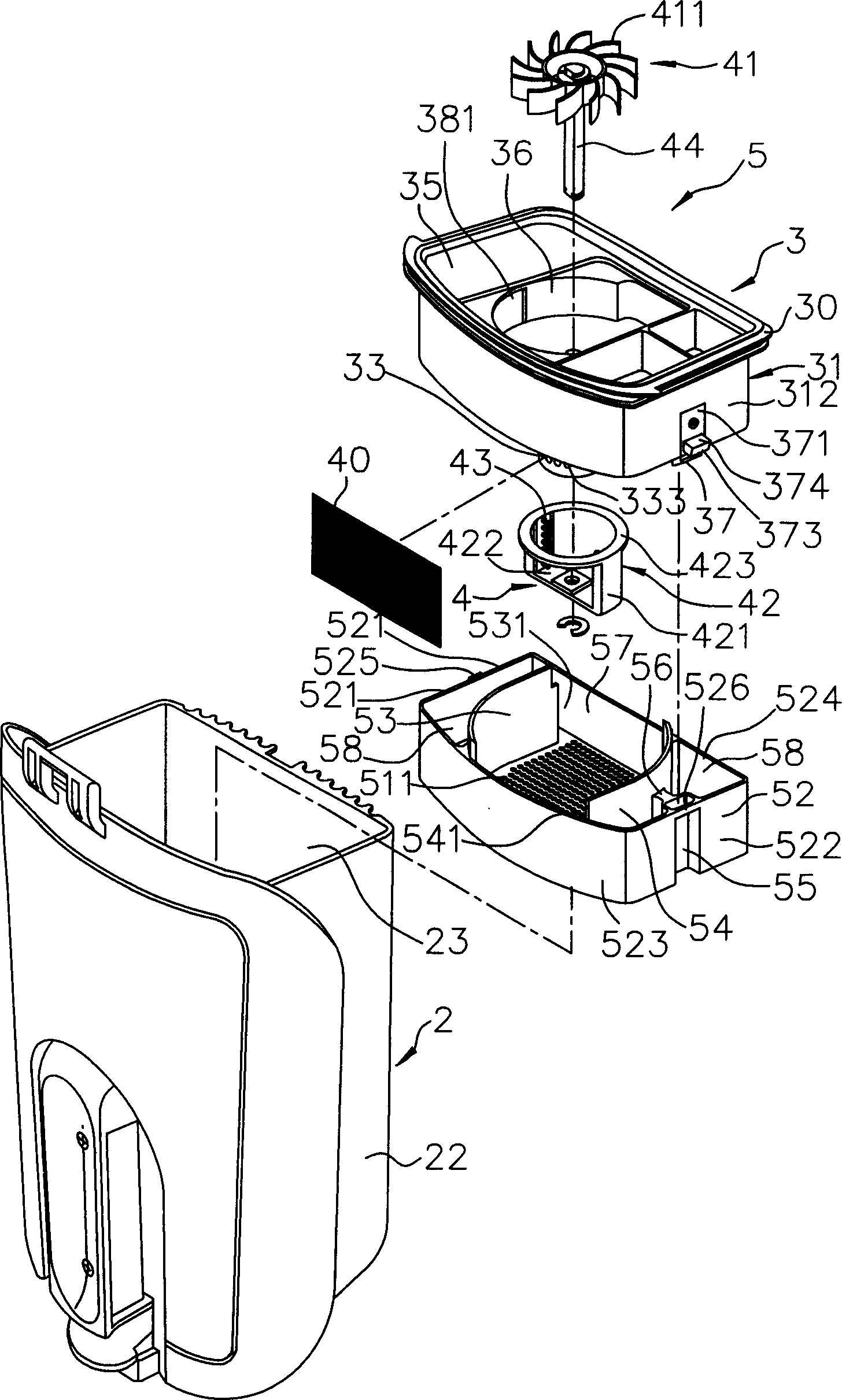
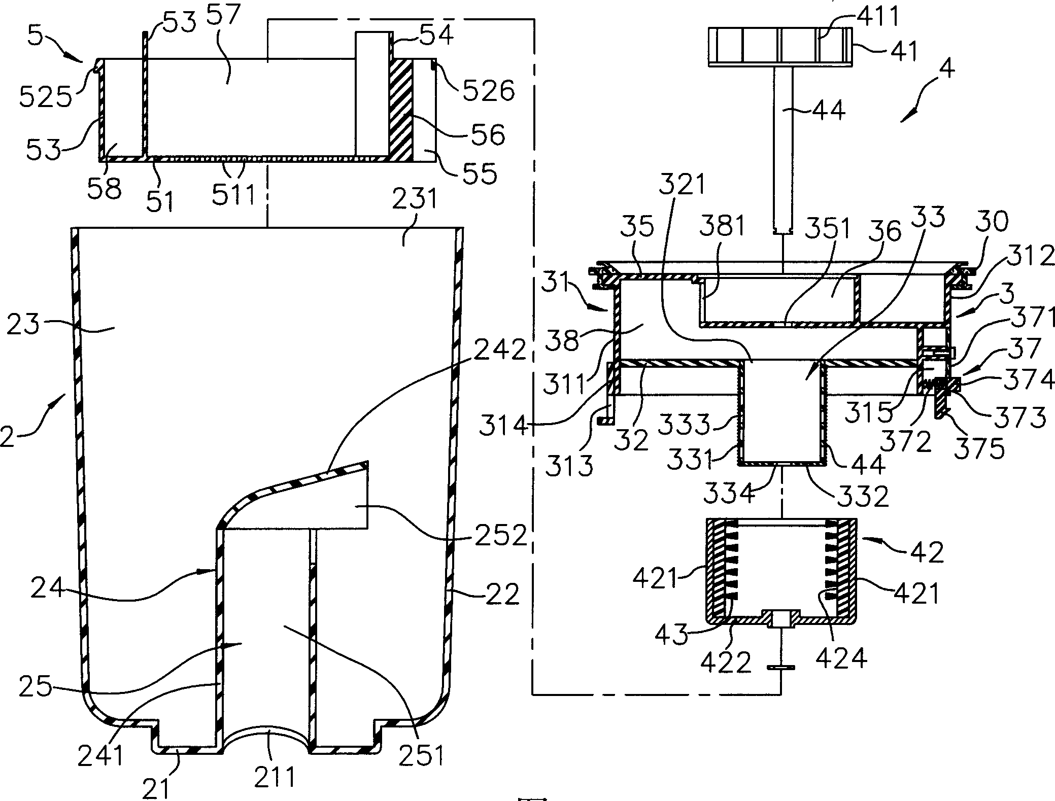
[0018] The dust collecting device 10 of the first prefe...


PUM


Abstract

A dust-collection device installed in the dust collector, which is installed between an air-inlet and an air-outlet of the dust collector; comprising a dust collection seat with a dust collecting room; the said dust collecting seat can connect with an installation stand or a primary declutch carrier alternatively detachably for the reason of different inner structure; the dust collection device also includes a dust brushing unit in the dust removing room and installed in the dust collecting seat or the installation stand; the said dust brushing unit can rotate automatically because of the air flow generated when the dust collector acts and thus removing the dust in the dust collecting net to reach the effect of no accumulation of dust in the dust collecting net where the air flow goes in and out and prolonging the maintenance period of the dust collection device and enhancing the application convenience.

Description

Technical field [0001] The invention relates to a part of a vacuum cleaner, in particular to a dust collecting device installed between the suction port and the air outlet of the vacuum cleaner for collecting dust in the air. Background technique [0002] In the prior art, although there are various structures of vacuum cleaners, the principle of their use is roughly the same, that is, the use of a motor to drive the rotation of the fan blades to generate suction, so that the air near the suction port passes through an internal dust collector. Then it is discharged from the air outlet. Some of the aforementioned dust collection devices are in the form of dust collection bags, and some are containers with at least one dust collection space. However, regardless of the structure of the dust collection device, dust tends to concentrate nearby when the general vacuum cleaner is in use. The position of the air outlet. This situation will affect the smoothness of the air flow. Therefore...

Claims


Application Information

Patent Timeline
Patent Type & Authority Applications(China)
IPC IPC(8): A47L9/10
Inventor 李希宏
Owner TSANN KUEN CHINA ENTERPRISE
Why Eureka
Try Eureka