Top cover of compressor

A compressor and discharge pipe technology, applied in mechanical equipment, machines/engines, liquid variable capacity machinery, etc., can solve the problems of reducing the refrigeration capacity and inflow of the compressor, improve the refrigeration capacity and reduce impurities entering the circulation pipeline the dangerous effect of

Inactive Publication Date: 2006-04-26
LG ELECTRONICS (TIANJIN) APPLIANCES CO LTD
View PDF0 Cites 0 Cited by
  • Summary
  • Abstract
  • Description
  • Claims
  • Application Information

AI Technical Summary

Problems solved by technology

When the compressor is running, the high-temperature and high-pressure gaseous refrigerant compressed by the compression mechanism can be discharged from the discharge pipe 2 into the circulation pipeline together with the lubricating oil in

Method used


Image

  • Top cover of compressor
  • Top cover of compressor
  • Top cover of compressor

Examples


Embodiment Construction

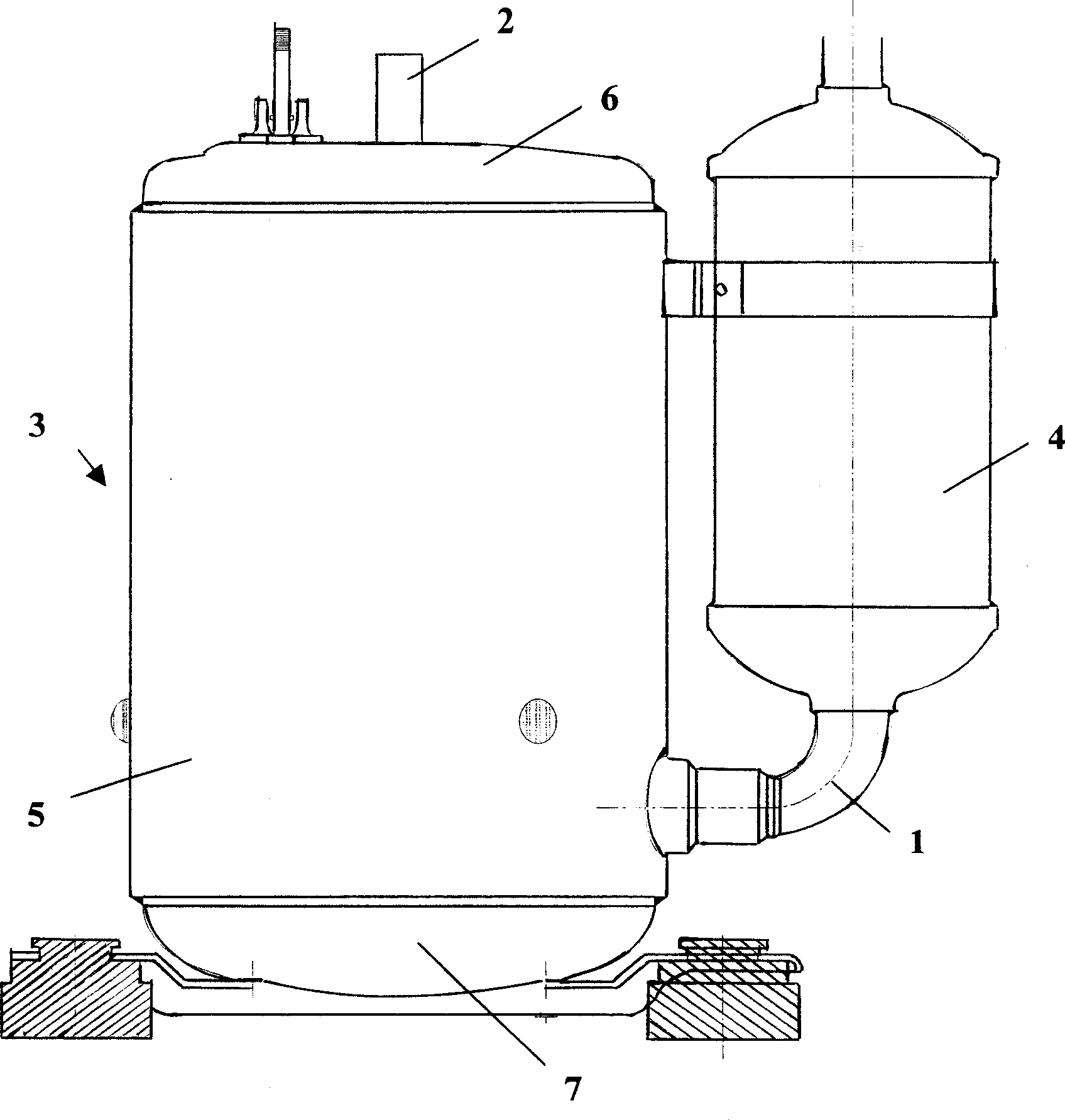
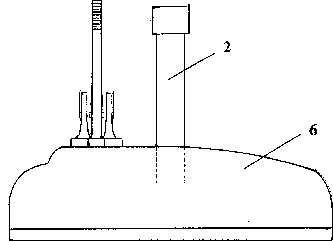
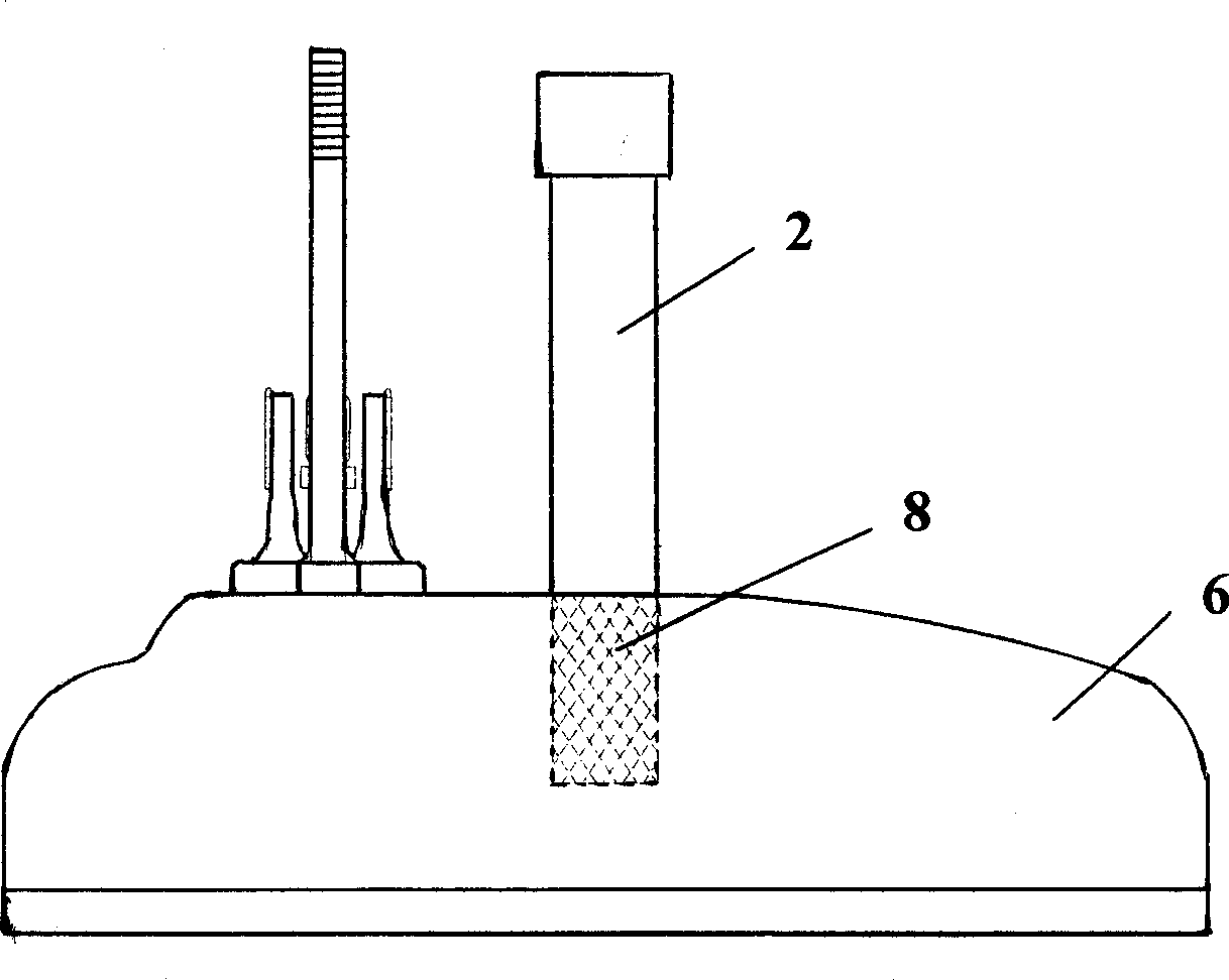
[0011] Such as image 3 As shown, a discharge pipe 2 is vertically provided at the center of the upper cover 6 of the compressor provided by the present invention, and a filter device 8 capable of filtering impurities in the refrigerant and lubricating oil is provided at the lower end of the discharge pipe 2 . The filtering device 8 is a mesh screen. When the compressor provided by the present invention is in operation, the refrigerant sucked into the airtight casing 3 through the suction pipe 1 can be compressed in the compression mechanical part set inside it to become a high temperature and high pressure state, and compressed by the compression mechanical part to high temperature and high pressure The gaseous refrigerant can be discharged into the circulation system together with the lubricating oil inside the compressor from the discharge pipe 2 arranged in the center of the upper cover 6. Since the lower end of the discharge pipe 2 is provided with a filter device 8, the ...


PUM


Abstract

The invention discloses a compressor top cover, which is characterized by the following: setting an outlet pipe on the central part of top cover vertically; fixing a mesh sieve filter device on the bottom of outlet pipe to remove coolant and lubricating oil, which reduces the danger of foreign material into circulation pipe path as well as improves the compressor cooling ability.

Description

technical field [0001] The invention relates to a compressor upper cover, in particular to a compressor upper cover equipped with a filter device. Background technique [0002] Generally speaking, a compressor is a device capable of compressing fluid, which usually consists of a sealed casing with an internal space, an electromechanical part installed in the sealed casing and providing driving force, and a compressor driven by the electromechanical part to compress the refrigerant. Composition of Compression Machinery Department. figure 1 It is a schematic diagram of the external structure of the compressor in the prior art. figure 2 for figure 1 Sectional view of the structure of the upper cover of the compressor in . Such as figure 1 , figure 2 As shown, this prior art compressor is internally provided with an electric mechanical part and a compression mechanical part not shown in the figure, and the lower part is provided with a suction pipe 1 which can suck the re...

Claims


Application Information

Patent Timeline
IPC IPC(8): F04B39/12F04B39/16F04C29/00
Inventor 王苏豫
Owner LG ELECTRONICS (TIANJIN) APPLIANCES CO LTD
Why Eureka
Try Eureka