Radiation device for reducing indoor air humidity

An indoor air humidity and radiation device technology, applied in the field of radiation devices, can solve the problems of increasing the investment cost of special dehumidification equipment, the failure of the air conditioning system to operate normally, and increasing the energy consumption of the dehumidification system, so as to ensure indoor comfort and cooling effect Good, simple structure effect

Inactive Publication Date: 2018-12-28
SOUTHEAST UNIV
6 Cites 0 Cited by

AI-Extracted Technical Summary

Problems solved by technology

[0003] However, the existing radiant panels have low cooling capacity and are prone to condensation, so they can only bear the sensible heat load in the room.
In order to solve this problem, it is usually necessary to configure a special dehumidification system to bear the indoor humidity load. At the same time, in order to prevent the occurrence of condensation, the water supply temperature of the system must be strictly controlled. This method not only increases the investment cost of the special ...

Abstract

The invention discloses a radiation device for reducing indoor air humidity. The radiation device body comprises a radiation device body, the radiation device body comprises a cold water circulation system, a radiation plate and a heat preservation layer, the middle of the radiation plate and the heat preservation layer is the cold water circulation system, a super-hydrophobic base is arranged onone side which is different from the cold water circulation system, of the radiation plate, a plurality of hydrophobic micro-grooves are uniformly distributed in the bottom of the super-hydrophobic base, needle-shaped hydrophilic bionic structures are arranged in the hydrophobic micro-grooves, the needle-shaped hydrophilic bionic structure is arranged on the hydrophobic micro-grooves randomly or at equal intervals. According to the radiation device, the problem of condensation of an existing radiation plate is effectively solved, the indoor air humidity can be greatly reduced, and the coolingcapacity of the radiation plate can be improved, the indoor comfort is guaranteed. The device is simple in structure and convenient to use, and cooling effect is relatively good and can be widely applied to high-temperature and high-humidity regions.

Application Domain

Technology Topic

Image

  • Radiation device for reducing indoor air humidity
  • Radiation device for reducing indoor air humidity
  • Radiation device for reducing indoor air humidity

Examples

  • Experimental program(1)

Example Embodiment

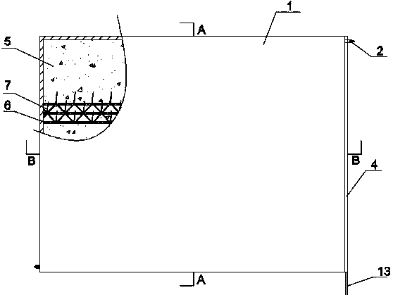
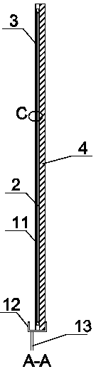
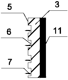
[0015] Such as Figure 1-4 As shown, the radiation device body 1 includes a cold water circulation system 2, a radiant plate 3, and an insulation layer 4. The radiant plate 3 made of copper or aluminum is a rectangular flat plate with a thickness of 1 to 2 mm. The radiant plate 3 is different from the cold water circulation system 2. There is a superhydrophobic substrate 5 on one side of the superhydrophobic substrate 5. Several hydrophobic microgrooves 6 with a width of 0.1~10mm and a depth of 0.1~5mm are evenly distributed on the superhydrophobic substrate 5. The angle between the hydrophobic microgrooves 6 is 0~90° The needle-like hydrophilic bionic structure 7 with a length of 0.1~30mm is arranged randomly and disorderly or equidistantly. The hydrophilic region and super-hydrophobic region are organically combined, and the needle-like hydrophilic bionic structure 7 can quickly trap the air. Water vapor molecules reduce the humidity of indoor air. Equally spaced arrangement includes two ways: in-line and crossed. The needle-shaped hydrophilic bionic structure 7 is made of copper, carbon steel, stainless steel, aluminum or nanoporous ceramic materials. The gap between the cold water circulation system 2 and the radiation plate 3 is provided with a metal fin 11 with a thickness of 2 to 3 mm, and the metal fin 11 is made of copper or aluminum. The bottom of the radiation device body 1 is provided with a condensed water receiving pan 12, and the condensing water receiving pan 12 is connected with a condensate drain pipe 13 to discharge the condensed water generated on the surface of the radiant panel 3. The superhydrophobic substrate 5 formed after the surface of the radiation plate 3 is modified. The superhydrophobic substrate 5 has a micro-nano binary surface structure and the rolling angle is less than 6°. The rolling resistance of the superhydrophobic substrate 5 surface is small, which is conducive to the rolling of droplets. When condensed water is generated on the surface of the radiant panel 3, it is easy to fall off from the surface of the radiant panel 3, which is beneficial to the discharge of condensate droplets.
[0016] Such as Figure 5 The cold water circulation system 2 includes a number of water supply branch pipes 8, a water supply main pipe 9 and a return water main pipe 10. The water supply branch pipe 8 is connected to the water supply main pipe 9 and the return water main pipe 10 respectively. The water supply branch pipe 8 is arranged in parallel, and the distance between the water supply branch pipes 8 is 30 ~90mm. The equivalent outer diameter of the water supply branch pipe 8 is 8-20 mm, the equivalent outer diameter of the water supply main pipe 9 is 15-25 mm, and the equivalent outer diameter of the return water main pipe 10 is 15-25 mm. The cold water produced by the water chiller flows through the circulating pipe to reduce the surface temperature of the metal fin 11 and the radiant plate 3 to form a cold radiant surface. The thermal insulation material restricts the heat transfer direction of the radiant panel 3, so that more cold energy is transferred to the indoor working area.

PUM

PropertyMeasurementUnit
Length0.1 ~ 30.0mm
Spacing30.0 ~ 90.0mm
Thickness2.0 ~ 3.0mm
tensileMPa
Particle sizePa
strength10

Description & Claims & Application Information

We can also present the details of the Description, Claims and Application information to help users get a comprehensive understanding of the technical details of the patent, such as background art, summary of invention, brief description of drawings, description of embodiments, and other original content. On the other hand, users can also determine the specific scope of protection of the technology through the list of claims; as well as understand the changes in the life cycle of the technology with the presentation of the patent timeline. Login to view more.

Similar technology patents

Selective garbage screening and feeding device and method

InactiveCN102950109AReduce humidityFor subsequent sortingSievingScreeningCrankDrive motor
Owner:BEIJING HAOHAI TIANJI TECH +1

Swimming goggle

ActiveUS20190381361A1Optimal level of comfort and efficacyReduce humidityDetails involving processing stepsImage analysisEngineering
Owner:ADIDAS

Classification and recommendation of technical efficacy words

  • Improve cooling capacity
  • Reduce humidity

Method for converting methanol into propylene

InactiveCN101830769AImprove cooling capacityIncrease raw material throughputHydrocarbon from oxygen organic compoundsBulk chemical productionDimethyl etherCarbon atom
Owner:ZHEJIANG UNIV

Integrated air conditioner

InactiveCN102022787AImprove heat exchange capacityImprove cooling capacityEnergy recovery in ventilation and heatingCondensate preventionIndoor airEvaporator
Owner:LG ELECTRONICS (TIANJIN) APPLIANCES CO LTD

Method for preparing olefin polymer by utilizing multiple temperature reaction areas

ActiveCN104628904AImprove cooling capacityHigh space-time yieldHeat transfer efficiencyFluidized bed
Owner:ZHEJIANG UNIV

Deodorization dehydrating device for cultivation

InactiveCN101336616AReduce ammonia odorReduce humidityAnimal housingBird housingsWinter seasonLivestock
Owner:马剑英
Why Eureka
Try Eureka