Exhaust pipe structure of compressor
An exhaust pipe and compressor technology, which is applied in the field of compressors, can solve the problems of reducing the refrigeration capacity of the compressor, loss of lubricating oil, and accelerated loss of lubricating oil, and achieve the effect of improving the refrigeration capacity
- Summary
- Abstract
- Description
- Claims
- Application Information
AI Technical Summary
Problems solved by technology
Method used
Image

Examples
Embodiment Construction
[0031] Hereinafter, the exhaust pipe structure of the compressor of the present invention will be described in detail with reference to the accompanying drawings and embodiments:
[0032] Parts and components that are the same in the present invention and the prior art use the same reference numerals.
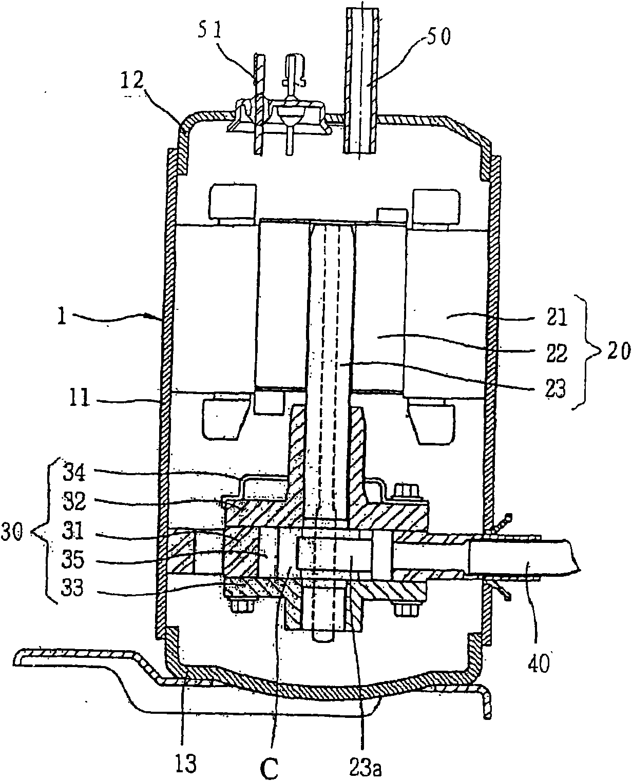
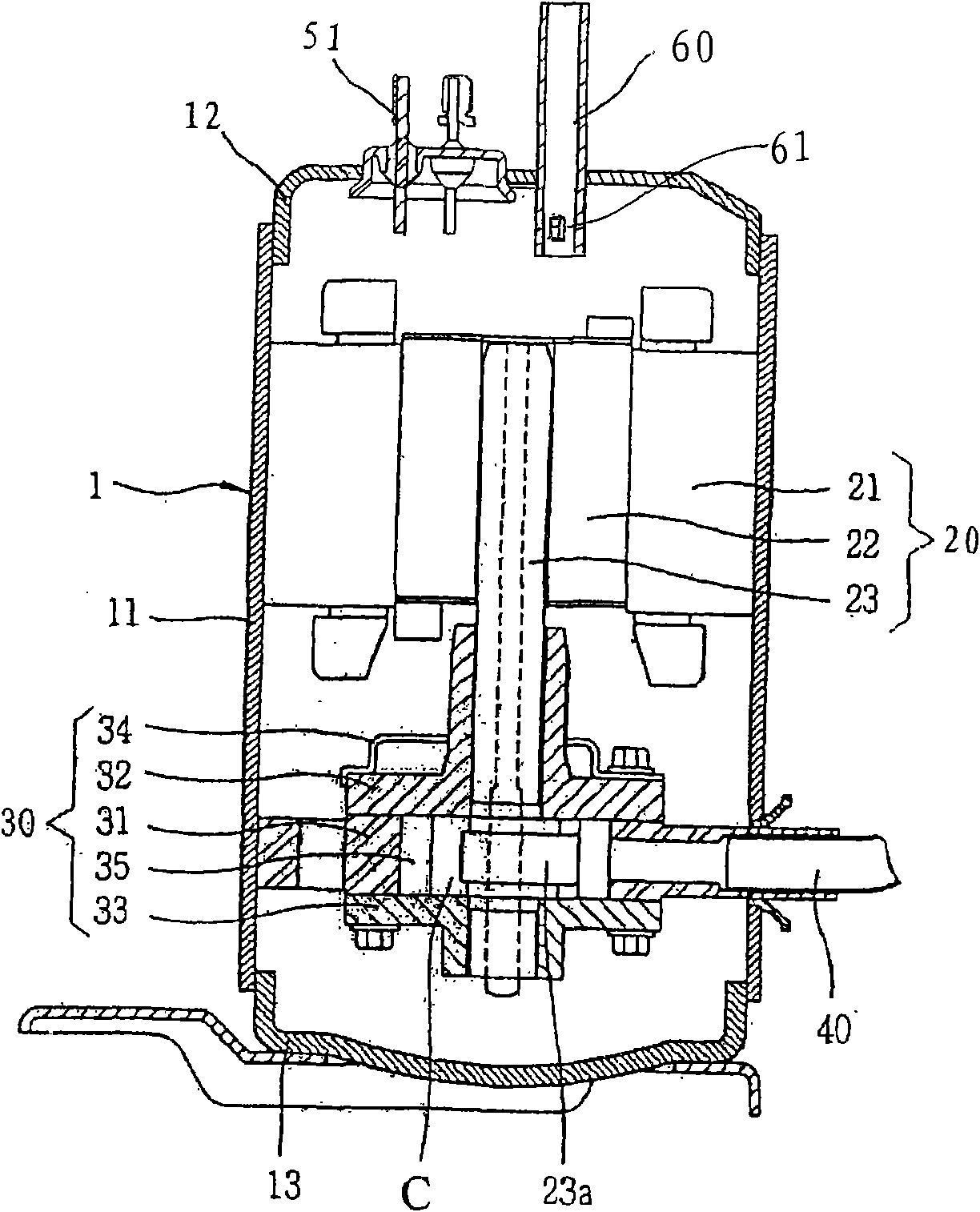
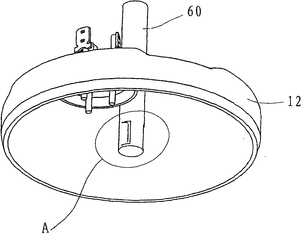
[0033] Such as Figure 1~5 As shown, a compressor exhaust pipe structure, the compressor includes a shell 1, the shell 1 is composed of a hollow cylindrical barrel 11, an upper cover 12 and a lower cover 13 and so on. A motor 20 is installed on the inner upper side of the housing 1, and the motor 20 is press-fitted and fixed on the inner peripheral surface of the cylinder 11. The motor 20 is fixed on the center of the rotor 22 by the stator 21, the rotor 22 and the center of the rotor 22 and transmits the rotational force. Rotary crankshaft 23 etc. are formed. A compressor assembly 30 is installed at a certain distance below the motor 20 . A compressor assembly 30 is install...
PUM
 Abstract
Description
Claims
Application Information