Method and device for controlling bias of optical modulator

A bias control and optical modulator technology, which is applied in the fields of instrumentation, optics, nonlinear optics, etc., can solve the problems of non-calibration and complicated DC bias control structure, and achieve the effect of simple bias control circuit.

Inactive Publication Date: 2006-04-26
SUMITOMO OSAKA CEMENT CO LTD
View PDF2 Cites 10 Cited by
  • Summary
  • Abstract
  • Description
  • Claims
  • Application Information

AI Technical Summary

Problems solved by technology

[0035] In this way, as the number of optical modulators increases, the configuration of the DC bias control of the optical modulator becomes complicated, and in order to measure the input-output characteristics of a specific optical modulator, other optical modulators are put in a non-operating state. Etc., in normal optical communication or optical measurement, there may be inappropriate situations such as non-correction

Method used


Image

  • Method and device for controlling bias of optical modulator
  • Method and device for controlling bias of optical modulator
  • Method and device for controlling bias of optical modulator

Examples


Embodiment Construction

[0072] Hereinafter, the present invention will be explained in detail using the best example.

[0073] Figure 4 It is a schematic diagram of an embodiment of the bias control device of the optical modulator of the present invention.

[0074] Light modulator 1, for figure 1 In the described nested light intensity modulator, light waves such as laser light enter the light modulator 1, receive a predetermined modulation while propagating in the light modulator 1, and start emission from the light modulator 1 as an optical signal.

[0075] Hereinafter, a nested light intensity modulator will be described as an example, but the present invention is not limited to this. If it is a light modulator composed of a combination of a plurality of light modulators (parts with an intensity modulation function or a phase modulation function), then The present invention is also applicable.

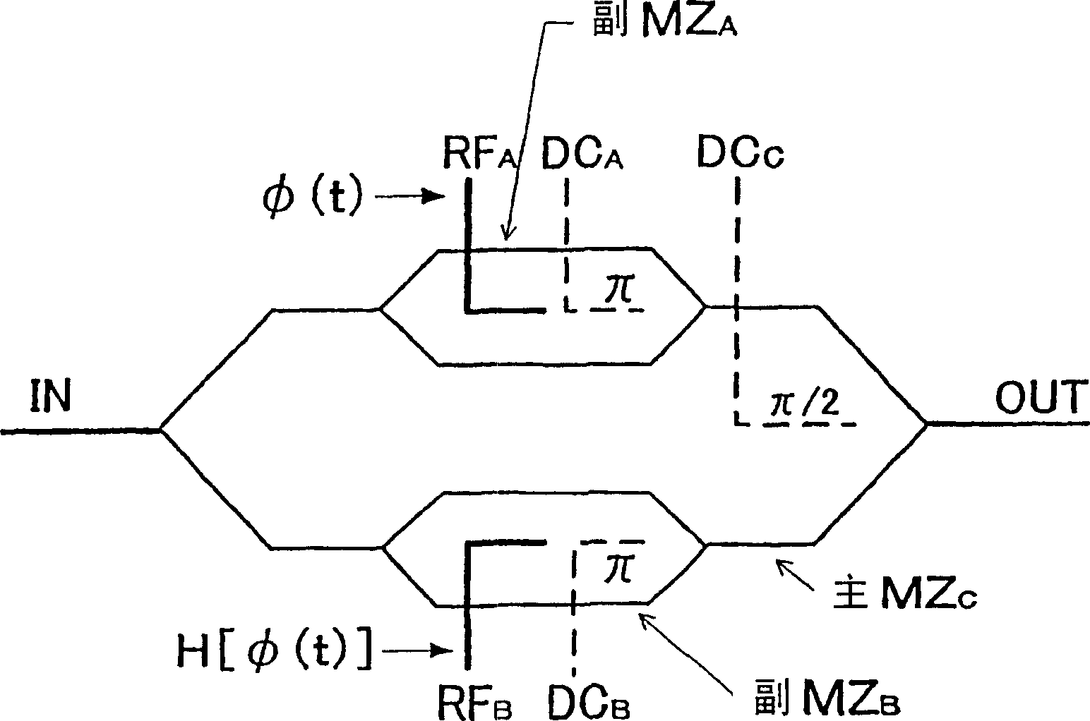
[0076] In the optical modulator 1, a sub-MZ-type optical waveguide path MZ is formed A , MZ B , And the ...


PUM


Abstract

An object of the present invention is to provide an optical modulator having a plurality of optical modulators, which can be configured with a simple structure, and can appropriately set the DC bias of each optical modulator during the normal operation of the optical modulator. A bias control method of a corrected optical modulator and an apparatus thereof. For an optical modulator (1) having a plurality of optical modulation sections, the bias control device (B) of the optical modulator for controlling the DC bias in the plurality of optical modulation sections includes: a DC bias applying mechanism (3) for applying a DC bias to the plurality of optical modulators; a low frequency signal (fB) superimposed on a modulation signal (b) applied to the plurality of optical modulators with a low frequency signal (fB) having a specific frequency A signal superimposition circuit (2); a photodetection mechanism (9) for detecting the light quantity change of the light wave passing through the wave superposition part; extracting the light quantity change corresponding to the low-frequency signal from the light detection mechanism, and simultaneously based on the extracted light quantity Change, a bias control mechanism (4) that controls the DC bias application mechanism.

Description

Technical field [0001] The present invention relates to a bias control method and device for an optical modulator, and more particularly to an optical modulator for optimally controlling the DC bias of each optical modulator for an optical modulator having a plurality of optical modulators inside. And its device. Background technique [0002] In the field of optical communication or optical measurement, optical modulators are often used as electrical-optical conversion elements. [0003] As an example of an optical modulator, it is known to use LiNbO 3 (Lithium niobate) and other substrates with electro-optical effects. However, such optical modulators have different light output characteristics according to the amount of DC bias applied for drive control or changes in the temperature of the environment. It will change over time, which is the so-called drift phenomenon. [0004] As a method of suppressing such a drift phenomenon, there is the following Patent Document 1 or 2, whi...

Claims


Application Information

Patent Timeline
Patent Type & Authority Applications(China)
IPC IPC(8): G02F1/03G02F1/035
Inventor 桥本义浩市川润一郎日隈薰藤田贵久
Owner SUMITOMO OSAKA CEMENT CO LTD
Why Eureka
Try Eureka