Method and device for dye solution infiltrating better during dyeing

A dyeing device and dyeing solution technology, applied in the field of dyeing methods and dyeing equipment, can solve problems such as poor exchange and suboptimal dye solution exchange, and achieve the effect of improving the exchange effect and improving the penetration effect

Inactive Publication Date: 2006-05-10
德科国际有限公司
View PDF1 Cites 4 Cited by
  • Summary
  • Abstract
  • Description
  • Claims
  • Application Information

AI Technical Summary

Benefits of technology

The new type of dye-spinning process improves how well two different types of liquid are mixed together when they come into contact during spinning processes on fabrics. This results in better mixing efficiency for both materials compared to previous methods that had only one material inside them.

Problems solved by technology

Technological Problem addressed in this patents relates to optimizing the use of dyes in industrial processes like printing without excessive wastewater production. Existing solutions involve changing detergments based solely upon their ability to pass through the fabric' s fiber bundle. Additionally, existing techniques require multiple steps involving separate stages of treatment followed by an intervention period until complete removal of any stains occurs.

Method used


Image

  • Method and device for dye solution infiltrating better during dyeing
  • Method and device for dye solution infiltrating better during dyeing
  • Method and device for dye solution infiltrating better during dyeing

Examples


Embodiment 1

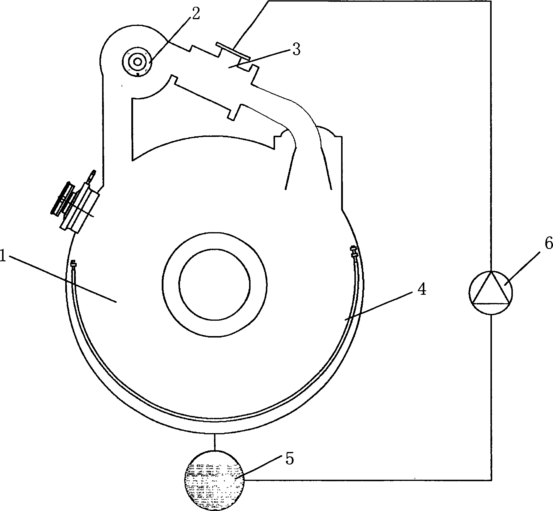
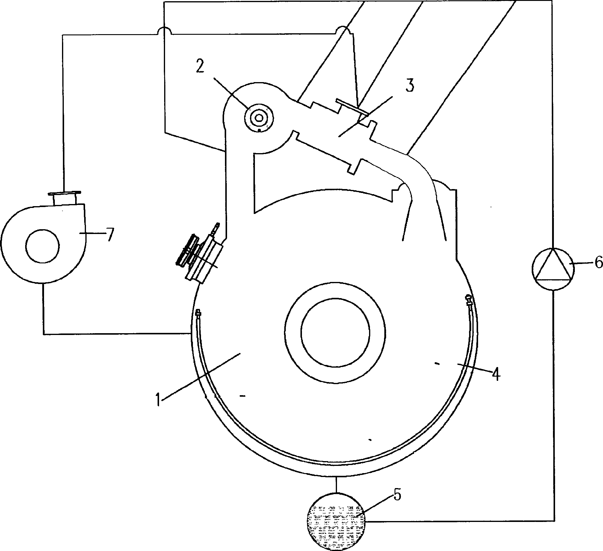
[0043] In one embodiment of the technical solution of the present invention, adopt figure 2 The basic structure of the dyeing machine shown is a pneumatic dyeing machine, which includes a pressure-resistant cylinder, a cloth shaft 2, a transmission medium nozzle 3 (air flow nozzle), a cloth storage chamber 4, a dye liquor tank 5, a pump 6 and a blower 7, etc. Wherein, the fabric bundle 1 is joined into a loop of the fabric bundle 1 that can be circulated in the dyeing machine barrel. The cloth beam 2 pulls the fabric bundle 1 upwards and introduces a pressurized transport medium such as air flow (air or a mixture of air and steam) through air flow nozzles 3 . The blower 7 draws air or a mixture of air and steam from the dyeing machine cylinder and presses it into the transfer medium nozzle 3 . In this way, the fabric circulates in the cylinder of the dyeing machine through the cloth shaft and the airflow introduced into the nozzle 3 . The pump 6 sucks the dye solution from ...

Embodiment 2

[0045] In another embodiment of the technical solution of the present invention, also adopt figure 2 The basic structure of the dyeing machine shown is a pneumatic dyeing machine, which includes a pressure-resistant cylinder, a cloth shaft 2, a transmission medium nozzle 3 (air flow nozzle), a cloth storage chamber 4, a dye liquor tank 5, a pump 6 and a blower 7, etc. Wherein, the fabric bundle 1 is joined into a loop of the fabric bundle 1 that can be circulated in the dyeing machine barrel. The cloth beam 2 pulls the fabric bundle 1 upwards and introduces a pressurized transport medium such as air flow (air or a mixture of air and steam) through air flow nozzles 3 . The blower 7 draws air or a mixture of air and steam from the dyeing machine cylinder and presses it into the transfer medium nozzle 3 . In this way, the fabric circulates in the cylinder of the dyeing machine through the cloth shaft and the airflow introduced into the nozzle 3 . The pump 6 sucks the dye solut...

Embodiment 3

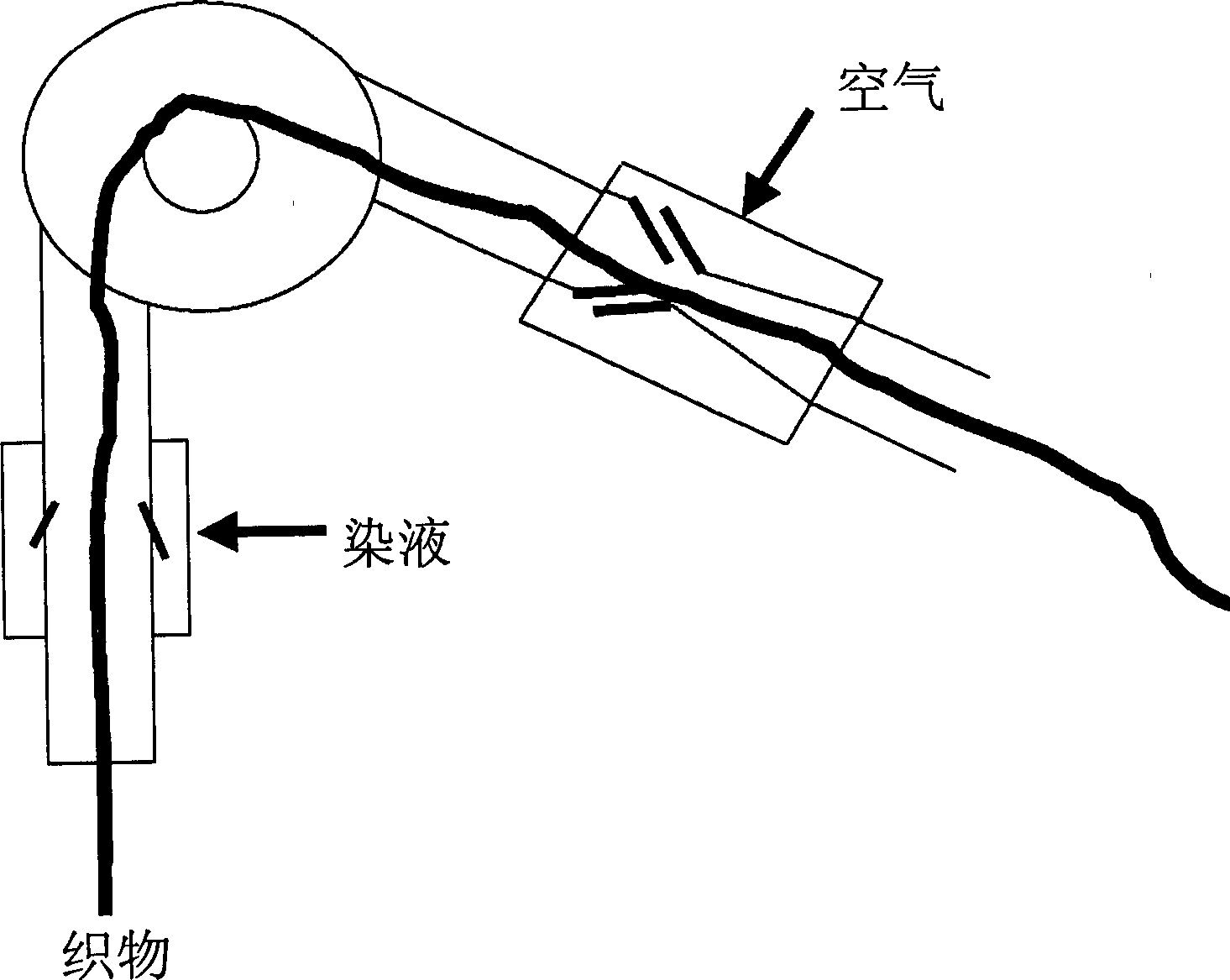
[0047] Implementation in the present embodiment is basically the same as in Example 1, except that the dye solution nozzle is arranged after the air flow nozzle 3, and the dye solution flow sprayed onto the fabric bundle 1 is against the moving direction of the fabric bundle 1.


PUM


Abstract

This invention provides a dyeing method and its device for the dyeing liquid dyes the fabric. In this invention, the nip angle between the eject direction of the dyeing liquid and the moving direction of the fabrics is at least 90íÒ, or opposite. Comparing to the present technology, this invention can improve the filter effect of the dyeing liquid in the fabrics.

Description


Claims


Application Information

Patent Timeline
Owner 德科国际有限公司
Why Eureka
Try Eureka