
Cylinder lock

A plunger, unlocking technology, applied in the direction of building locks, buildings, building structures, etc., can solve the problems of inability to perform unlocking operations, complicated operations, etc., and achieve the effect of improving the efficiency of assembly operations

Inactive Publication Date: 2011-03-09
HONDA LOCK MFG CO LTD
View PDF0 Cites 0 Cited by
  • Summary
  • Abstract
  • Description
  • Claims
  • Application Information

AI Technical Summary

Problems solved by technology

Then, even if the mating key is inserted and turned again, only the rotor turns and the plunger does not move, thus causing a problem that the normal unlocking operation cannot be performed because the link is not connected with the rotor
[0006] Also, the plunger locks described above involve a problem in that assembling multiple components requires complex operations and requires specific or specialized jigs

Method used


Image

  • Cylinder lock
  • Cylinder lock
  • Cylinder lock

Examples


Embodiment 1

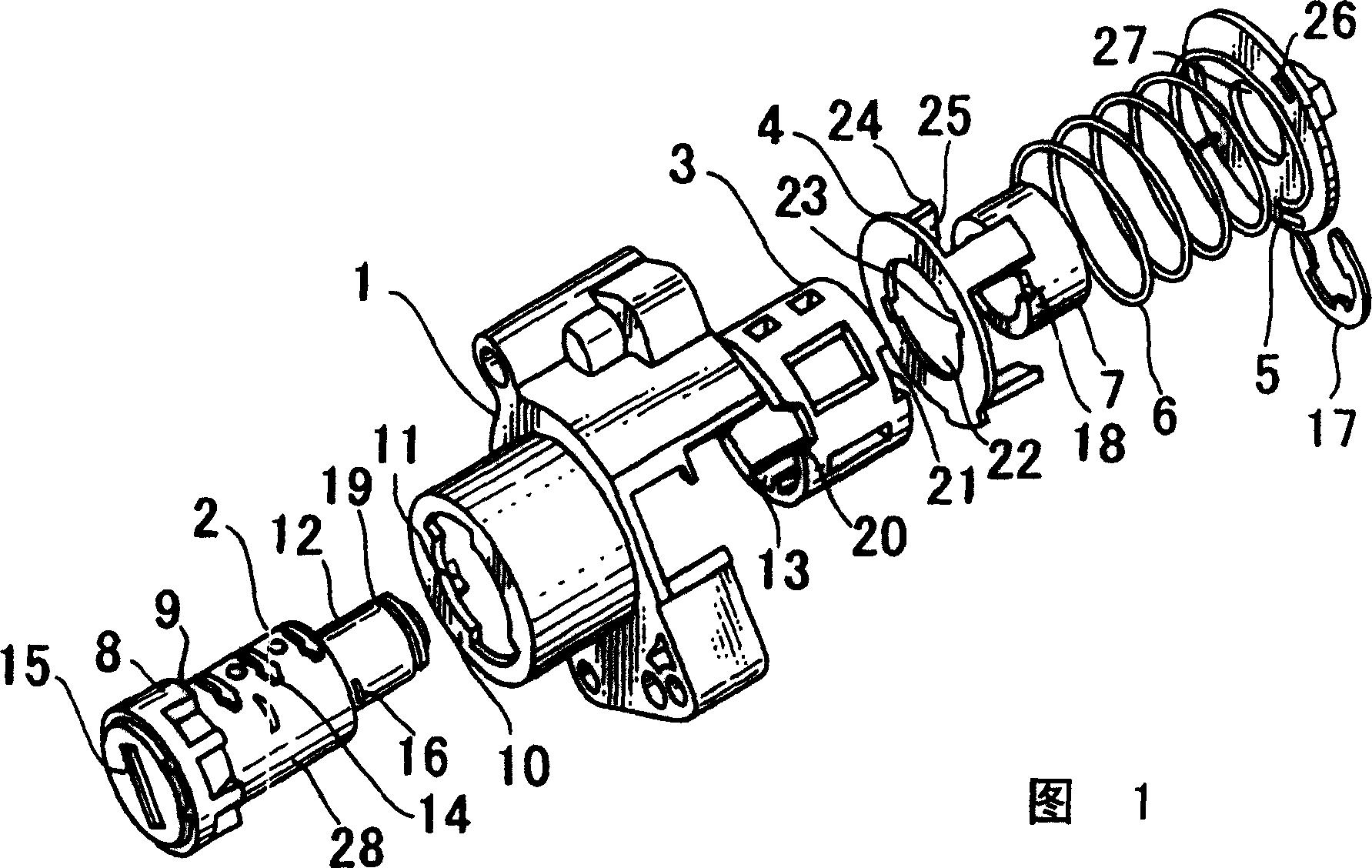
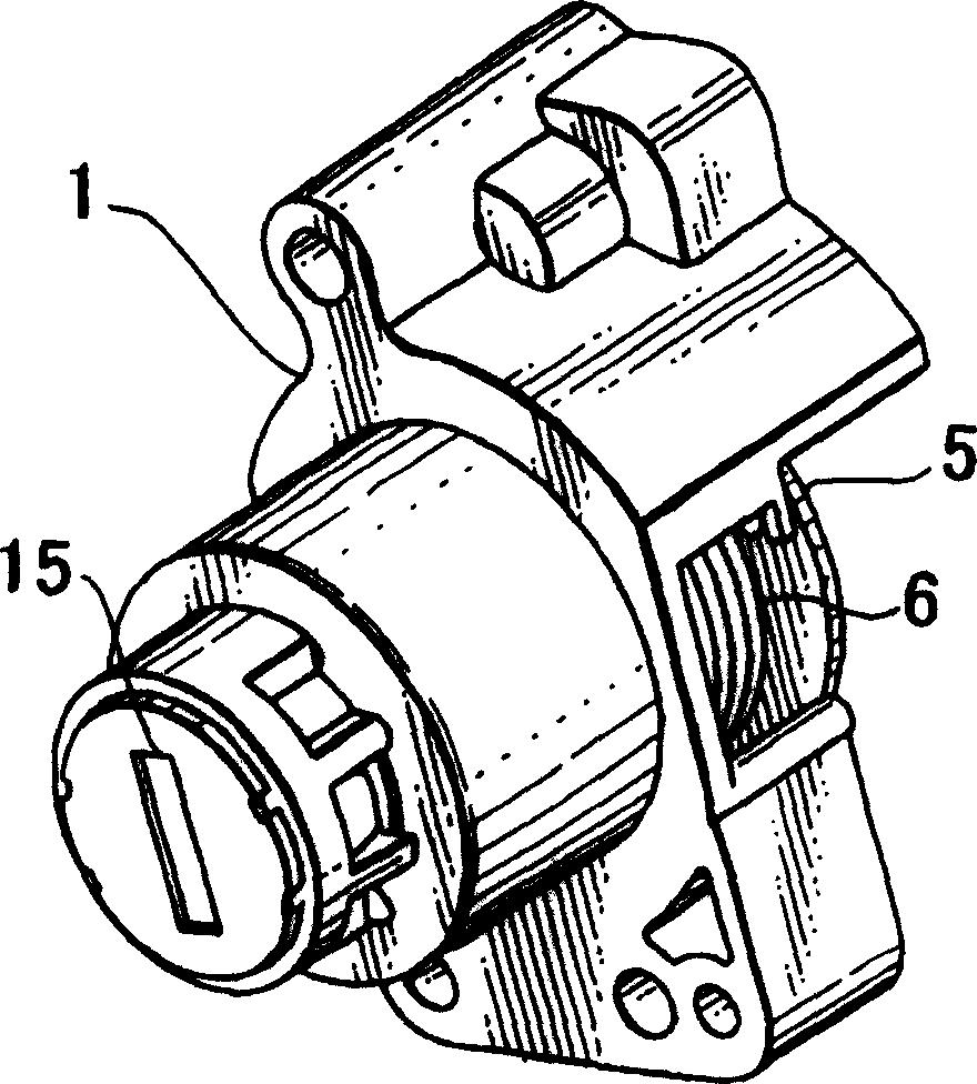
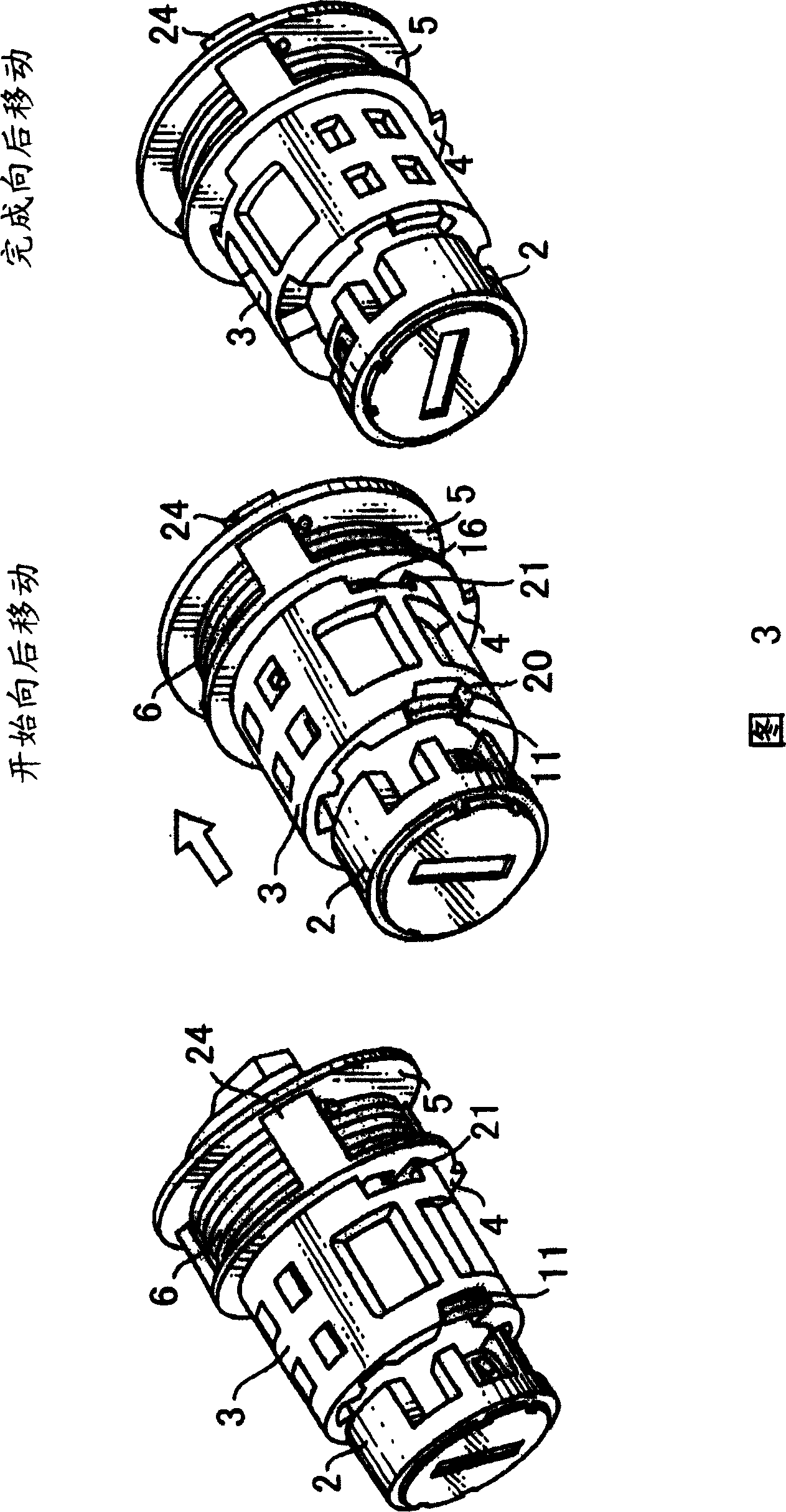
[0048] [Example 1]( figure 1 to Figure 4)

[0049] Such as figure 1 and figure 2 As shown, the plunger lock according to Embodiment 1 of the present invention includes a housing 1, a rotor 2, a cylindrical plunger 3, an unlocking element 5, a connecting piece 4, a return spring 6 and a collar 7, and the housing 1 is fixed on the On the opening / closing part of the vehicle, the rotor 2 has a stepped diameter and is rotatably installed in the housing 1, with a retractable tumbler, the plunger 3 is rotatably arranged between the rotor 2 and the housing 1, and the unlocking element 5 is connected The rear end of the rotor 2 , the connecting piece 4 and the return spring 6 are detachably mounted on the rear end of the rotor 2 , and the collar 7 is located between the connecting piece 4 and the return spring 6 .

[0050] More specifically refer to figure 1Each component has adjoining portions 10 opposite to each other on the outer periphery of the front edge of the housing 1 , w...

Embodiment 2

[0067] [Example 2] ( Figure 5 to Figure 15 )

[0068] Embodiment 2 and additional modified embodiments according to the present invention will be described below with reference to the drawings.

[0069] Embodiment 2 and the like have the following technical features: that is, the connecting piece, spring, and unlocking element in Embodiment 1 are assembled into a whole in advance, so as to facilitate the assembly operation of the plunger lock.

[0070] Such as Figure 5 and Figure 6 As shown, the plunger lock according to Embodiment 2 of the present invention includes a housing 101, a rotor 102, a cylindrical plunger 103, an unlocking element 105, a connecting piece 104, a return spring 106 and a collar 107, and the housing 101 is fixed as On the opening / closing part of the vehicle of the base body, the rotor 102 has a stepped diameter and is rotatably installed in the housing 101, with a retractable tumbler, the plunger 103 is rotatably arranged between the rotor 102 and...


PUM


Abstract

A cylinder lock capable of normal unlocking operation by an authorized key to a locking mechanism which has been illegally operated by an unauthorized key or the like, the cylinder lock comprising an engaging portion that engages a rotor in the rotational direction only when the cylinder moves toward the unlocking member is disposed to a cylinder to engage the rotor and the cylinder thereby rotating the rotor upon subsequent insertion of an authorized key to connect the rotor and the connection member thereby enabling normal unlocking operation.

Description

technical field [0001] The present invention relates to a plunger lock for locking and unlocking a door locking device used, for example, on a vehicle, and more particularly, to a plunger lock capable of preventing illegal unlocking of the locking device. Background technique [0002] Plunger locks generally include a housing having a bayonet and being fixed to a base (such as a vehicle body), a rotor having a retractable tumbler rotatably disposed within the housing, and a small diameter portion connected to the rotor and An unlocking element operatively associated with a locking device. In the above structure, when the matching key is inserted and the rotor is turned, the tumbler can be retracted from the outer peripheral surface of the rotor, and then the rotor can be turned within the housing. Thus, the unlocking element can also rotate with the rotor, making it possible to lock and unlock the locking device via a transmission element, such as a lever. [0003] Convers...

Claims


Application Information

Patent Timeline
Patent Type & Authority Patents(China)
IPC IPC(8): E05B17/20
Inventor 由比一郎石塚贵士
Owner HONDA LOCK MFG CO LTD
Learn More