
Driving device for terry motion members in cloth-shifting-type pile-loop loom

A driving device and cloth moving technology, applied in flannel looms, looms, textiles, etc., can solve the problems of warp damage, wrong cutting of looms, operator injury, etc., and achieve effective effects and prevent warp damage.

Active Publication Date: 2006-05-24
TSUDAKOMA KOGYO KK
View PDF1 Cites 5 Cited by
  • Summary
  • Abstract
  • Description
  • Claims
  • Application Information

AI Technical Summary

Problems solved by technology

At this time, there may be a weaving problem as follows: Forcible force acts on the ground warp yarn wound on the loop member on the let-off side, causing damage to the ground warp yarn.
[0007] Moreover, when the loom stops for some reason, the operator may operate close to the loom in order to repair the cause of the stop, and this operation may also be performed near the loop member on the let-off side or the take-up side.
In this way, when the operator operates near the loop member on the let-off side or the take-up side, if other operators do not notice or turn off the power supply of the loom by mistake, the following safety problems will arise : The looping part moves suddenly due to its own weight, collides with the operator's hand and injures the operator
[0008] Moreover, when the loom is temporarily stopped, if the power supply of the loom is cut off, the loop members on the let-off side and the take-up side are displaced from the position when the loom is stopped due to their own weight, and the synchronous state with the loom is significantly deviated.
In this case, the synchronous adjustment operation performed when the loom is restarted is cumbersome and takes a lot of time.

Method used


Image

  • Driving device for terry motion members in cloth-shifting-type pile-loop loom
  • Driving device for terry motion members in cloth-shifting-type pile-loop loom
  • Driving device for terry motion members in cloth-shifting-type pile-loop loom

Examples


Embodiment Construction

[0019] Hereinafter, embodiments of the present invention will be described in detail with reference to the drawings.

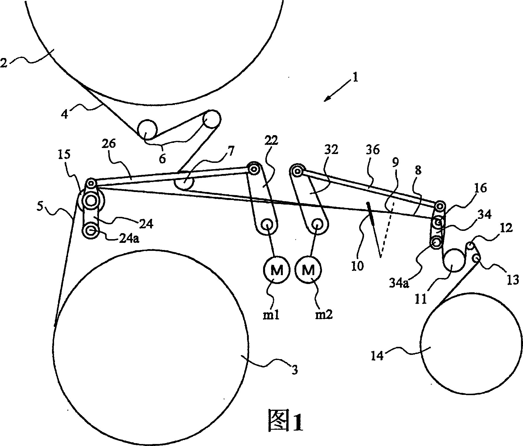
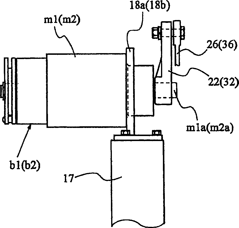
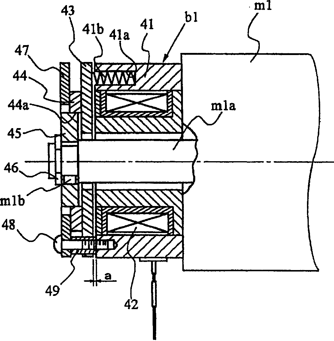
[0020] In Figure 1~ image 3 In one embodiment of the present invention shown, the illustrated terry loom 1 which is the object of the present invention is a cloth moving type terry loom that moves a cloth fell during the process of terry weaving to form piles.

[0021] Cloth mobile terry loom 1 has: warp beam 2 for terry warp yarns (upper side of the drawing), a plurality of terry warp yarns 4 rolled and pasted in sheet form; warp beam 3 for ground warp yarns (lower side of the drawing), A plurality of ground warp yarns 5 are pasted in a sheet form. The pile warp yarn 4 is sent out from the warp beam 2, is wound around two guide rollers 6, 6 and the outer periphery of the pile warp yarn tension roller 7 arranged on the downstream side thereof, is guided, and then passes through a heald (not shown) and The reed 10 is guided to the cloth fell 9 of the cloth 8...


PUM


Abstract

When the power supply to the drive motor for driving the loop members is stopped, a braking force is applied to the loop members on the let-off side and the take-up side to prevent them from being freely movable. In the terry loom that drives the terry components by a dedicated drive motor, a braking device is additionally provided in the driving mechanism of the terry components, and the braking device is used for driving the terry components. When the power supply is stopped, the movement of the loop parts is prevented.

Description

technical field [0001] The present invention relates to a driving device for a terry member, and in particular to a cloth movement in which the terry members on the let-off side and the take-up side are driven by a separate dedicated drive motor different from the main drive motor of the loom The driving device of the pile part of the type pile loom. Background technique [0002] As a cloth moving type terry loom of the above-mentioned form, there is a structure described in Patent Document 1, for example. [0003] Patent Document 1: JP-A-2-47334 [0004] In the cloth moving type terry loom described in Patent Document 1, single or separately provided rollers are used for the back roller as the terry member on the let-off side and the bridge as the terry member on the take-up side. Driven by a dedicated drive motor. [0005] In this type of cloth moving type terry loom, if the power supply to the drive motor for driving the terry parts is stopped, the terry parts will ope...

Claims


Application Information

Patent Timeline
Patent Type & Authority Applications(China)
IPC IPC(8): D03D39/22D03D49/04
CPCD03D39/223
Inventor 伴场秀树山本昭彦角田博
Owner TSUDAKOMA KOGYO KK
Learn More