Resonant point regulating circuit

A technology for adjusting circuits and resonance points, which is applied in the field of wireless power transmission, can solve problems such as difficulty in obtaining the best resonance point, unsuitability for mass production, and difficulty in implementation, so as to achieve self-adaptive adjustment, optimization of resonance quality, and improved charging The effect of potency

Inactive Publication Date: 2006-05-24
张定港 +1
View PDF0 Cites 4 Cited by
  • Summary
  • Abstract
  • Description
  • Claims
  • Application Information

AI Technical Summary

Problems solved by technology

[0007] However, in this way of adjusting the capacitance C or inductance L to meet the frequency F, the variation of the capacitance C or inductance L due to the tolerance error of the parts during implementation is not only difficult to obtain the best resonance point, which affects performance, but also due to this Variables must be adjusted on-site by professional technicians and equipment, which is difficult to implement and not suitable for mass production

Method used


Image

  • Resonant point regulating circuit
  • Resonant point regulating circuit
  • Resonant point regulating circuit

Examples


Embodiment Construction

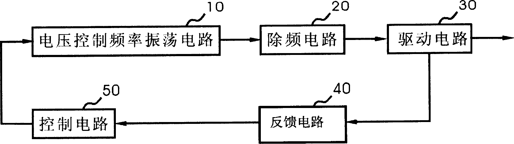
[0020] see figure 1 , the resonance point adjustment circuit of the present invention includes: a voltage-controlled frequency oscillation circuit 10, a filter circuit 20, a drive circuit 30, a feedback circuit 40 and a control circuit 50, when the voltage-controlled frequency oscillation circuit 10 is generated by the filter circuit 20 When the oscillation frequency is output by the drive circuit 30, the feedback circuit 40 can feed back the output frequency of the drive circuit 30 to the control circuit 50, and after the control circuit 50 obtains the best resonance point, then control the output of the oscillation frequency of the voltage control frequency oscillation circuit 10 , so that the resonance quality can be optimized to improve performance. When the drive circuit 30 outputs the oscillation frequency, the oscillation frequency is fed back to the control circuit 50 through the feedback circuit 40, so that the control circuit 50 analyzes and obtains the optimum reson...


PUM


Abstract

The regulator circuit includes generation circuit of oscillatory waveform, filter circuit, drive circuit, feedback circuit and control circuit. Output end of the generation circuit of oscillatory waveform is connected to the input end of the filter circuit. The output end of the filter circuit is connected to the input end of the drive circuit. The output end of the drive circuit is connected to the input end of the feedback circuit. The output end of the feedback circuit is connected to the input end of the control circuit. The output end of the control circuit is connected to the input end of the generation circuit of oscillatory waveform. Being output from the drive circuit, the oscillation frequency through the feedback circuit is fed to the control circuit. After analyzing and obtaining optimum resonance point, the control circuit controls the generation circuit of oscillatory waveform to output optimized frequency so as to realize self-adaptive control of oscillatory frequency.

Description

technical field [0001] The invention relates to the field of wireless power transmission, in particular to a circuit for adjusting oscillation frequency. Background technique [0002] In the existing wireless power transmission technology, the most common method is to transmit an electromagnetic field to an iron powder core, use the iron powder core to guide the electromagnetic field to another induction coil, and generate electricity through the induction coil. However, this wireless power transmission mode is often limited by the height and shape configuration of the powdered iron core and induction coil, and needs to be used on relatively large devices, and is not suitable for small portable electronic products. For example, an electric toothbrush is charged in this way, so that the electric toothbrush does not need to be provided with a disposable battery or an external power cord; but this mode is not suitable for small portable electronic products such as MP3PLAYER. ...

Claims


Application Information

Patent Timeline
Patent Type & Authority Applications(China)
IPC IPC(8): H03J5/00
Inventor 张定港林荣聪
Owner 张定港
Why Eureka
Try Eureka